
Circuit Diagram
Index 2192
Pyroelectric infrared detector and its application circuit diagram
Published:2011/3/31 3:19:00 Author:Jessie | Keyword: Pyroelectric infrared detector, application
View full Circuit Diagram | Comments | Reading(600)
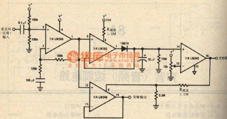
Pyroelectric infrared language alarm circuit
Published:2011/3/31 3:50:00 Author:Jessie | Keyword: Pyroelectric infrared language alarm
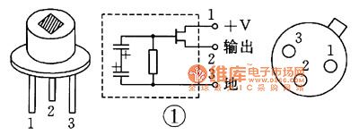
Pyroelectric infrared language alarm isuse pyroelectricity infrared sensor as the probe todetect human body's special wavelength infrared signal. Non-contact detection distance, that is the body close to the protected areas' vision, alarm devicewill send outwarninglanguage. Sensor'sspectral rangeis 1 ~ 10μm, center is 6 μm, all All are in infrared bands, is decided by the optical properties of silicon window which packed in TO-5 metal shell.
(View)
View full Circuit Diagram | Comments | Reading(832)
Pyroelectric infrared language alarm device selection circuit
Published:2011/3/30 3:09:00 Author:Jessie | Keyword: infrared language, alarm device
Pyroelectric infrared sensor modelcan choose P2288 or LS064, need to match 120 ° 12m wide-angle Fresnel filter glass. IC1 choose SNS9201 integrated circuit or SS0001 application-specific integrated circuit. IC2is language integrated circuits BA08, it storesstatement of Dangerous, there is electricity, keep away , IC2is soft encapsulation. IC3 is a integrate circuit with four languages analog sound, working voltageis 2 4 ~ 5 5V, soft encapsulation.
(View)
View full Circuit Diagram | Comments | Reading(676)
10-bit low-power digital temperature sensor application circuit
Published:2011/3/23 3:04:00 Author:Joan | Keyword: low-power , digital temperature sensor , application circuit
Below is 10-bit low-power digital temperature sensor application circuit.
(View)
View full Circuit Diagram | Comments | Reading(790)
Voice-control switch and amplifier circuit
Published:2011/3/23 3:02:00 Author:Joan | Keyword: Voice-control switch , amplifier , Voice-control
Below is Voice-control switch and amplifier circuit.
(View)
View full Circuit Diagram | Comments | Reading(590)
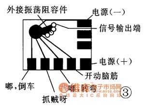
Acoustic control four tones doll principle circuit diagram
Published:2011/3/28 1:30:00 Author:Joan | Keyword: Acoustic control , four tones , doll
This circuit uses the FL-11 blocks. It has few external components and its device is simple. Connect a ready acoustic control PCB to 2 1/4 inch speakers. Load into a box, and then external connect toFour AA batteries storm cells and support. Switch on, put into the doll body. When clapping, the doll cries of father, mother. It sounds like real one. the circuit generally can be succeed by different debug.
(View)
View full Circuit Diagram | Comments | Reading(912)
Voice-control doll PCB circuit
Published:2011/3/23 3:00:00 Author:Joan | Keyword: Voice-control doll , PCB , Voice-control
Below is Voice-control doll PCB circuit.
(View)
View full Circuit Diagram | Comments | Reading(561)
Jetta interior light, luggage light, license plate light circuit
Published:2011/3/23 20:37:00 Author:Joan | Keyword: Jetta , interior light , luggage light , license plate light
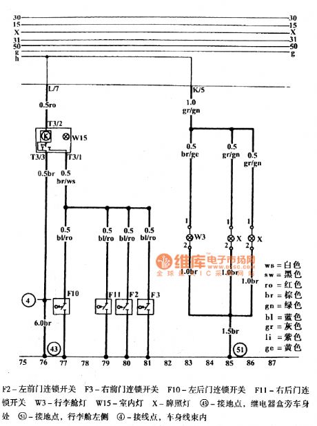
ws=whitesw=blackro=redbr=browngn=greenbl=bluegr=grayli=purplege=yellow
F2 - Left front door chain switchF3 - Right front door chain switchF10 - Left rear door chain switchF11 - Right rear door chain switchW3 - Luggage compartment lightW15 - Interior lightX - License plate lamp43 - Ground point, near the relay box next to the car body51 - Ground point, the left side of luggage compartment4 - Connection points, Within the body harness (View)
View full Circuit Diagram | Comments | Reading(891)
Jetta headlight, parking light, dimmer light and turn signal switch circuit
Published:2011/3/28 0:57:00 Author:Joan | Keyword: Jetta , headlight , parking light , dimmer light , turn signal switch
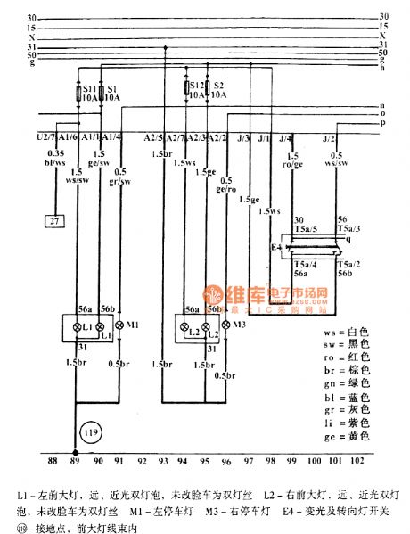
ws=whitesw=blackro=redbr=browngn=greenbl=bluegr=grayli=purplege=yellowL1-Left front headlight, Far, nearly two-lamp light, unchanged face automobile uses double filamentsL2-Right front headlight, Far, nearly two-lamp light, unchanged face automobile uses double filamentsM1-Left parking lightM3-Right parking lightE4-Varying light and turn signal switch119-Ground point, in the front headlight wire harness
Above isJetta headlight, parking light, dimmer light and turn signal switch circuit.
(View)
View full Circuit Diagram | Comments | Reading(1492)
Multi-functional fountain bonsai operation principle circuit
Published:2011/3/27 23:03:00 Author:Joan | Keyword: Multi-functional fountain bonsai , operation principle
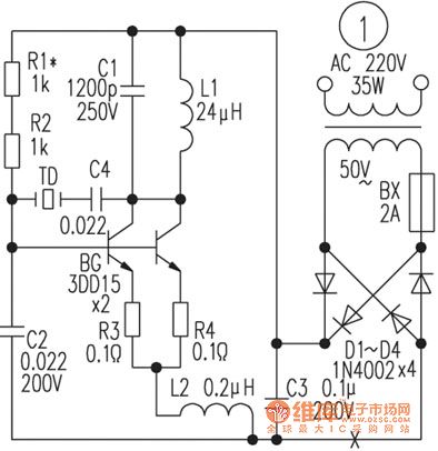
It is a high-power and high-frequency oscillator using capacitive three-point oscillating circuit. The circuit oscillation frequency is piezoelectric transducer TD’s natural frequency 1.3MHz. L1 and C1 form a resonant circuit which does not determine the oscillation frequency here, but decided the oscillation amplitude. Its resonant frequency is 0.6MHz lower than the circuit's oscillation frequency. L2 and C2 oscillation frequency is greater than the circuit resonant frequency. The reason for using two resonant circuits, is to make the oscillation frequency of the circuit is more pure. To make the work of the oscillator is stable in the high-power, it uses two transistors to parallel work. R1, R2 are bias resistors. R1 is adjusted to make the oscillator output moderate. R3, R4 are used to balance the two transistors. (View)
View full Circuit Diagram | Comments | Reading(1182)
Jetta front and rear fog lamp circuit
Published:2011/3/27 22:42:00 Author:Joan | Keyword: Jetta , fog lamp
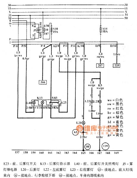
E23-Front and rear fog lamp switchK13-Rear fog lamp indicatorL40-Front, rear fog lamp switchJ5-Fog light relayL20-Rear fog lampL22-Left front fog lampL23-Right front lamp119-Ground point, Within the headlight wiring harness50-Ground point, in the lower part of the luggage compartment lock63-Ground point, in the car body internal wire harness
Above is Jetta front and rear fog lamp circuit. (View)
View full Circuit Diagram | Comments | Reading(1057)
Jetta manual system, fuel pump, fuel level sensor circuit
Published:2011/3/27 20:58:00 Author:Joan | Keyword: Jetta , manual system , fuel pump , fuel level sensor
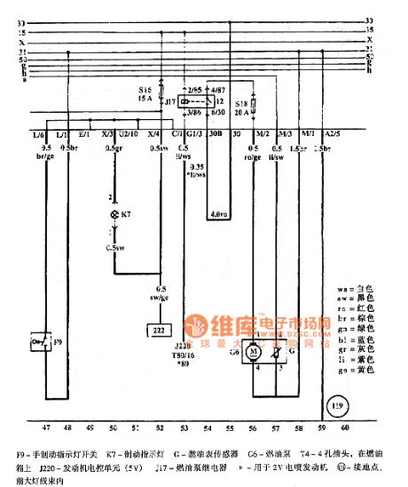
Above is Jetta manual system, fuel pump, fuel level sensor circuit.
ws=whitesw=blackro=redbr=browngn=greenbl=bluegr=grayli=purplege=yellow
F9-Hand brake indicator light switchK7-Brake indicator lightG-Fuel gauge sensorC6-Fuel pumpT4-4-hole plug, on the fuel tankJ220-Engine (5Y)H-EFI engine for 2VM19-Ground point, in the headlight wire harness (View)
View full Circuit Diagram | Comments | Reading(1515)
Capacitive displacement transmitter circuit
Published:2011/3/24 1:30:00 Author:Joan | Keyword: displacement transmitter , Capacitive displacement transmitter
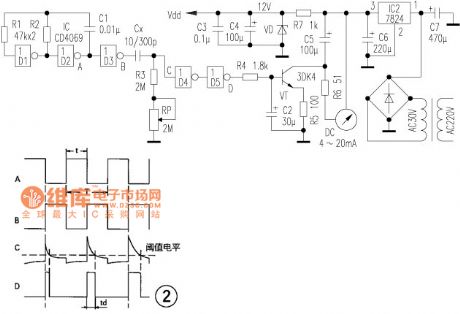
Circuit principle: the multivibrator signal is led out by D2 output. When D2 output is high, the monostable circuit is in a steady state, and D3 output, D4 input, D5 output are low voltage. When D2 output is low, the monostable circuit enters into the temporary stable state. When D3 outputs high voltage, it charges Cx through R3 and RP. Meanwhile, D5 outputs a high level into the U-I output stage, and D4 input voltage decreases exponentially with time. When the voltage is lower than D4 threshold level, the output jumps high, and then jump into a low voltage after being inverted by D5. When the square wave D2 outputted jumps high, Cx is then discharging through R3 and RP until D2 becomes high voltage, which completed a one-shot cycle. Waveform in each point is shown in Figure 2. The output pulse width td is proportional to Cx. The voltage, smoothed by R4 and C2, sent to VT base, is amplified and converted into 4 ~ 20mA DC uniform signal. (View)
View full Circuit Diagram | Comments | Reading(843)
Golf Bora airbag system schematic
Published:2011/3/23 22:05:00 Author:Joan | Keyword: Golf , Bora , airbag system
Above is Golf Bora airbag system schematic.
ws=whitesw=blackro=redbr=browngn=greenbl=bluegr=grayli=purplege=yellowor=orange
Airbag ECU, airbag coil spring, front airbag trigger, side airbag crash sensor
D-Ignition switchF138-Airbag coil springG179-Driver side airbag crash sensorG180-Front passenger side airbag crash sensorsH-Speaker control mechanismJ4-Two-tone horn relayJ234-Airbag ECU, Lower after vice dashboardN95-Driver side airbag triggerN131-Front passenger side airbag trigger 1T5b、T5j-Plug, 5-holeT75-Plug, 75-hole42-Ground point, near the steering column49-Ground point, On the steering column81-Ground point 1, in the instrument panel wiring harness109-Ground connection, in the airbag wiring harness135-Ground connection 2, in the instrument panel wiring harnessA2-Positive connection (15), in the instrument panel wiring harness
Airbag ECU, side airbag trigger, seat belt tension trigger
J17-Fuel pump relayJ234-Airbag ECU, after the lower part of vice dashboardJ379-Central lock and anti-theft ECUJ393-Comfort system central ECUN153-Driver side seat belt tension triggerN154-Front passenger side seat belt tension triggerN199-Driver side side airbag triggersN200-Front passenger side airbag triggerT2-plug, 2-hole, under the driver's seatT3a-plug, 2-hole, under the front passenger seatT23-plug, 23-holeT24-plug, 24-holeT75-plug, 75-holeA125-Connection (crash signal), in the instrument panel wiring harness**-Before April 2001---After May 2001
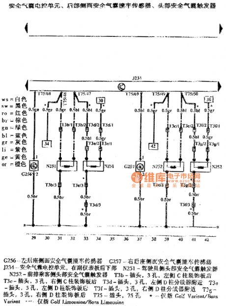
Airbag ECU, the rear side of the airbag crash sensor, the head airbag trigger
G256-Left rear seat side airbag crash sensor G257-The right rear seat side airbag crash sensorJ234-Airbag ECU, in the lower right of vice instrument panel N251-Driver side head airbag triggerN252-Front passenger side head airbag triggerT3b-Plug, 3-hole, behind the left C-pillar decorative panelT3c-Plug, 3-hole, behind the right of C-pillar decorative panelT3d-Plug, 3-hole, near the left of D column splitterT3e-Plug, 3-hole, behind the left of D column decorative panelT3f-Plug, 3-hole, near the right of D column splitterT3g-Plug, 3-hole, behind the right D column decorative panelT75-Plug, 75-hole*-Only refer to Golf Variant/Bora Variant---Only refer to Golf Limousine/Bora Limousine (View)
View full Circuit Diagram | Comments | Reading(1759)
Simple infrared alarm device circuit
Published:2011/3/30 2:25:00 Author:Jessie | Keyword: infrared, alarm device
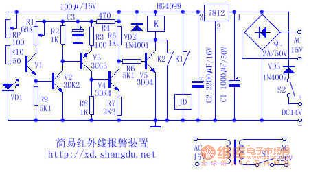
Infrared alarm device emits an infrared,can not be seen only by the naked eye, when anyone or object blocking any bunch of infrared light, alarm devicewill immediately makewarning signals.Using infraredto makealarm device, has advantages of concealed, high reliability, long life, strong anti-jamming capability, etc.
(View)
View full Circuit Diagram | Comments | Reading(1116)
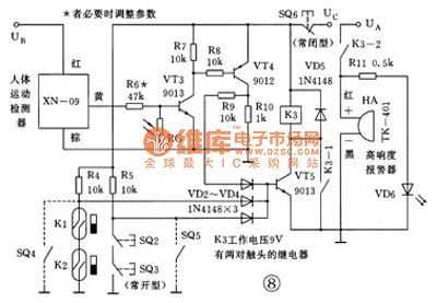
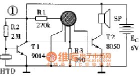
The human body induction alarm cat diagram
Published:2011/3/31 3:18:00 Author:Jessie | Keyword: human body induction alarm cat
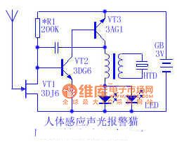
When debugging, first adjust oscillating circuit part,don't access mosfet to circuit temporarily. As long as oscillation part welding and correct, itwill send out Mimi quack, meanwhile leds can glow normal, changing the feedback capacitor C can change oscillation frequency, small capacity, high frequency, whereas low frequency. Then access mosfetto circuit, switch on the power, HTD calls appear, it's dueto human body's induction.
(View)
View full Circuit Diagram | Comments | Reading(781)
No external delay circuit diagram
Published:2011/3/25 2:30:00 Author:Rebekka | Keyword: No external delay
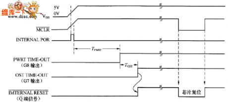
No external delay circuit diagram is shown as below.
(View)
View full Circuit Diagram | Comments | Reading(491)
External delay circuit diagram
Published:2011/3/25 2:32:00 Author:Rebekka | Keyword: External delay
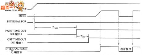
External delay circuit diagram is shown as below.
(View)
View full Circuit Diagram | Comments | Reading(541)
3.3V Voltage output power supply transforming circuit diagram
Published:2011/3/22 22:45:00 Author:Rebekka | Keyword: 3.3V Voltage output, power supply transforming
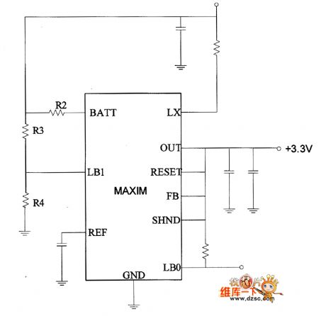
3.3V Voltage output power supply transforming circuit diagram is shown as below.
(View)
View full Circuit Diagram | Comments | Reading(894)
5V Voltage output power supply transforming circuit diagram
Published:2011/3/22 22:45:00 Author:Rebekka | Keyword: 5V Voltage output, power supply transforming
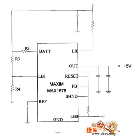
5V Voltage output power supply transformingcircuit diagram is shown as below.
(View)
View full Circuit Diagram | Comments | Reading(662)
| Pages:2192/2234 At 2021812182218321842185218621872188218921902191219221932194219521962197219821992200Under 20 |
Circuit Categories
power supply circuit
Amplifier Circuit
Basic Circuit
LED and Light Circuit
Sensor Circuit
Signal Processing
Electrical Equipment Circuit
Control Circuit
Remote Control Circuit
A/D-D/A Converter Circuit
Audio Circuit
Measuring and Test Circuit
Communication Circuit
Computer-Related Circuit
555 Circuit
Automotive Circuit
Repairing Circuit