
Circuit Diagram
Index 2199
Touch dimmer composed of LS7232
Published:2011/3/28 2:00:00 Author:Ecco | Keyword: Touch dimmer
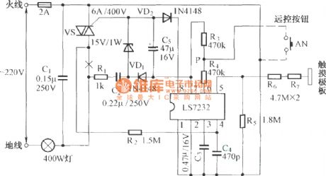
Touch dimmer composed of LS7232 is as below:
(View)
View full Circuit Diagram | Comments | Reading(1435)
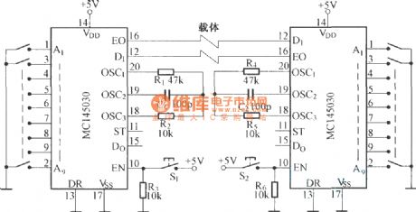
Duplex communication circuit diagram composed of MCl45030
Published:2011/3/28 2:02:00 Author:Ecco | Keyword: Duplex communication circuit
View full Circuit Diagram | Comments | Reading(771)
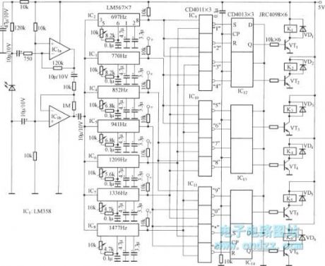
Six channel remote circuit diagram coded by LM567
Published:2011/3/28 1:56:00 Author:Ecco | Keyword: Six channel remote
View full Circuit Diagram | Comments | Reading(1584)
Rolling massage Bailing brand circuit diagram
Published:2011/3/30 3:13:00 Author:Rebekka | Keyword: Rolling massage, Bailing brand
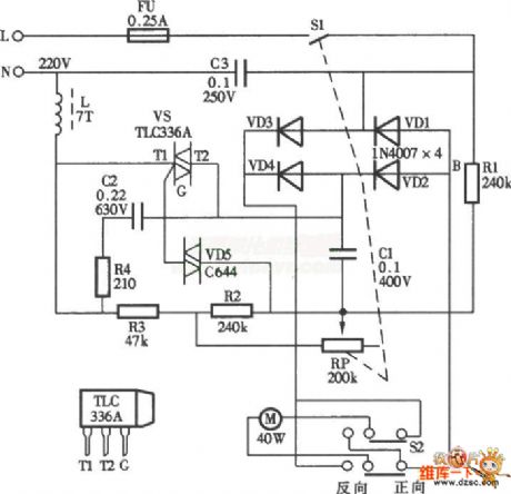
Here is the schematic diagram of the rolling massage Bailing brand circuit:
(View)
View full Circuit Diagram | Comments | Reading(762)
One port with the four connectors circuit diagram
Published:2011/3/30 2:26:00 Author:Rebekka | Keyword: One port with the four connectors
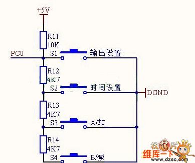
Here is the schematic diagram of the one port with the four connectorscircuit:
(View)
View full Circuit Diagram | Comments | Reading(486)
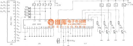
Four channel remote circuit diagram composed of ZHF-9901 and ZHJ-9902
Published:2011/3/28 1:51:00 Author:Ecco | Keyword: Four channel remote
View full Circuit Diagram | Comments | Reading(395)
51 SCM and PC serial port MAX232 circuit diagram
Published:2011/3/30 2:28:00 Author:Rebekka | Keyword: 51 SCM, PC serial port
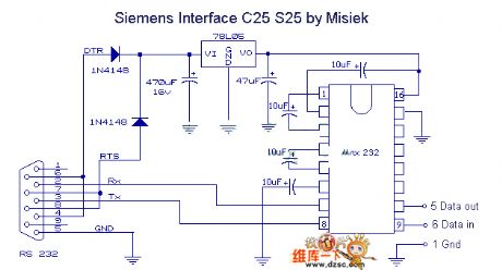
Here is the schematic diagram of the 51 SCM and PC serial port MAX232 circuit:
(View)
View full Circuit Diagram | Comments | Reading(4324)
The circuit diagram of sound controlling supply socket composed of transistor
Published:2011/3/28 1:19:00 Author:Ecco | Keyword: sound controlling supply socket , transistor
View full Circuit Diagram | Comments | Reading(468)
TDA2030 application circuit diagram
Published:2011/3/30 21:19:00 Author:Rebekka | Keyword: application circuit
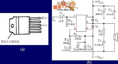
The shape and the pinout of TDA 2030 is shown as figure(a). The integrated amplifier has 5 feet. It has a simple connection line. It can be connected as OCL circuit and OTL circuit. It is widely used in audio equipments. The internal short circuit protection circuit has overheat protection. The main parameters are: power supply 6~18V, output power 9W, input impedance 5MΩ, voltage gain 30dB, harmonic distortion 0.2%. TDA 2030 typical application circuit diagram is shown as below.
(View)
View full Circuit Diagram | Comments | Reading(3328)
High input resistance inverting amplifier circuit diagram
Published:2011/3/30 2:31:00 Author:Rebekka | Keyword: High input resistance, inverting amplifier
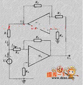
Here is the schematic diagram of the high input resistance inverting amplifier circuit:
(View)
View full Circuit Diagram | Comments | Reading(569)
The inside circuit diagram of crystal triode EMH15
Published:2011/3/30 21:50:00 Author:Ecco | Keyword: crystal triode
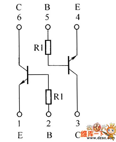
The inside circuit diagram of crystal triode EMH15 is as below:
(View)
View full Circuit Diagram | Comments | Reading(487)
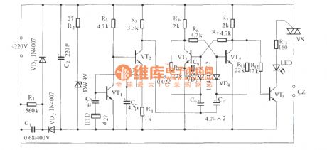
The exposure time control circuit diagram
Published:2011/3/30 21:49:00 Author:Ecco | Keyword: Time exposure
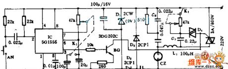
To assure the quality of the photogragh, this device can satisfy the shutterbug to control the time of exposure. It has the advantages of high accuracy in time controlling, having universal function such as time exposure, light-dimmer, pressure regulating and so on. Enlarging bulb or iron, electric blanket and lamp. The electric applianceses, such as electric fan and dynamo. etc. can be connected to the output socket CZ, and the output is controlled by the silicon capacity. For example, the pure resistive load can provide the power with 600 W; capacitive or inductive burden make the output be smaller than 300w.
(View)
View full Circuit Diagram | Comments | Reading(641)
The interface circuit diagram of the ADC0808/0809 and 8031
Published:2011/3/30 21:50:00 Author:Ecco | Keyword: The interface circuit
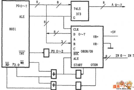
View full Circuit Diagram | Comments | Reading(1452)
The interface circuit diagram of the ADC0816/0817 and 8031
Published:2011/3/30 21:51:00 Author:Ecco | Keyword: The interface circuit
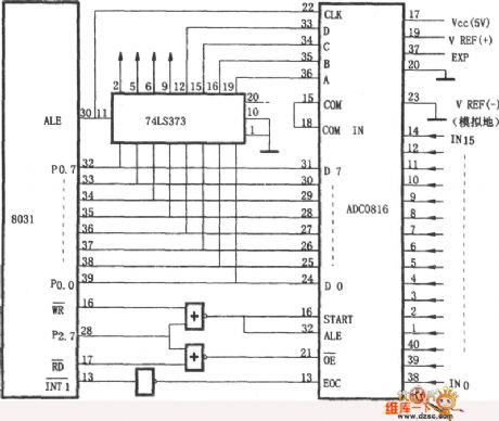
View full Circuit Diagram | Comments | Reading(1112)
The interface circuit diagram of the ADC0801~0805 and 8031
Published:2011/3/30 21:51:00 Author:Ecco | Keyword: interface circuit
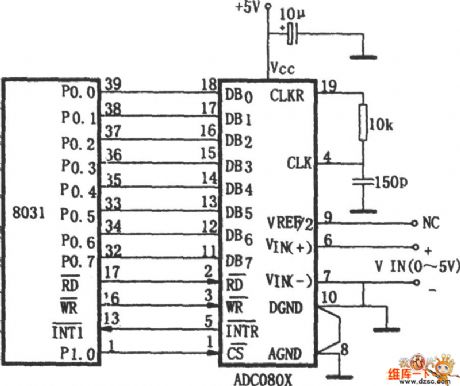
View full Circuit Diagram | Comments | Reading(1379)
The interface circuit diagram of the ADC0801~0805 and the microprocessor
Published:2011/3/30 21:42:00 Author:Ecco | Keyword: interface, microprocessor
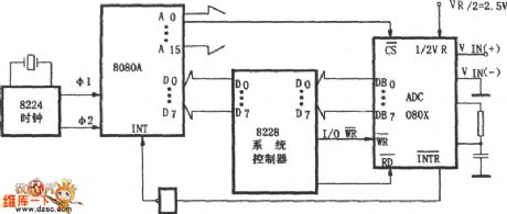
View full Circuit Diagram | Comments | Reading(630)
The circuit diagram of CAN-BUS of Audi A4 (2)
Published:2011/3/30 21:42:00 Author:Ecco | Keyword: Audi A4, CAN-BUS
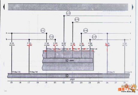
The circuit diagram of CAN-BUS of Audi A4 (2) is as below:
(View)
View full Circuit Diagram | Comments | Reading(2343)
Sensitive Oscillator Circuit Diagram
Published:2011/3/30 21:42:00 Author:Ecco | Keyword: Sensitive Oscillator
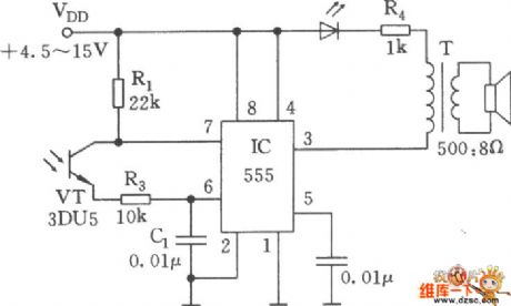
As shown as below, this oscillator is a type without steady-state harmony which composed of 555, R1, R3, C1 and optics triode VT. The internal resistance is changed with the illumination, and when the light is strong, it presents in low resistivity, when the light is weak, t presents in high resistivity. So the frequency of oscillator changes with the light in the range of 1Hz~6.5kHz. So the oscillator is available to make blind man to explore the way, early dawn report Xiao etc. situation.
(View)
View full Circuit Diagram | Comments | Reading(816)
6bm8 6as7 Power amplifier circuit diagram
Published:2011/3/30 21:33:00 Author:Ecco | Keyword: Power amplifier
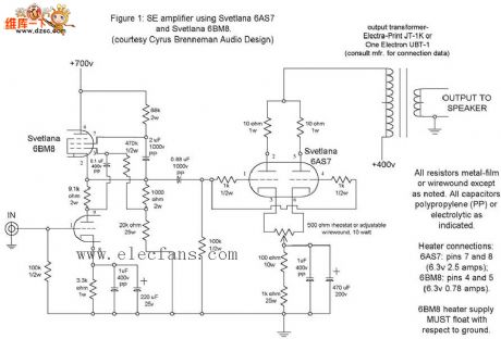
6bm8 6as7 Power amplifier circuit diagram is as below:
(View)
View full Circuit Diagram | Comments | Reading(6967)
Low power consumption monostable circuit diagram
Published:2011/3/30 21:40:00 Author:Ecco | Keyword: Low power consumption, monostable
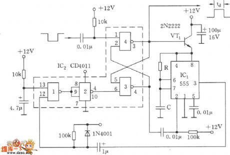
The circuitry shown as below, it includes a four 2 input port and NOT-gate CD4011 and a CMOS type 555, as a result whether it is inthe timing period of quiescent or high output level, it consumes very low. The portal 3 of CD4011, portal 4 constitute RS trigger. Because the whole circuitry presents in closed cycle, the pulse width is decided by the RC time constant, namely td=the 1.1 R1 C1.
(View)
View full Circuit Diagram | Comments | Reading(956)
| Pages:2199/2234 At 2021812182218321842185218621872188218921902191219221932194219521962197219821992200Under 20 |
Circuit Categories
power supply circuit
Amplifier Circuit
Basic Circuit
LED and Light Circuit
Sensor Circuit
Signal Processing
Electrical Equipment Circuit
Control Circuit
Remote Control Circuit
A/D-D/A Converter Circuit
Audio Circuit
Measuring and Test Circuit
Communication Circuit
Computer-Related Circuit
555 Circuit
Automotive Circuit
Repairing Circuit