
Circuit Diagram
Index 2198
Overvoltage protection integrated voltage regulator circuit consisting of CW137
Published:2011/3/28 3:53:00 Author:Joan | Keyword: Overvoltage protection , integrated voltage regulator
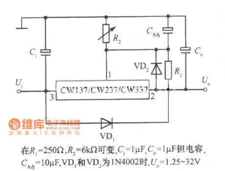
R1=250Ohm, R2=6kohm are variable, Ci=1uF, Co=1uF is tantalum capacitor, CAdj=10uF, when VD1 and VD2 are 1N4002, Uo=1.25~32V.
Above is Overvoltage protection integrated voltage regulator circuit consisting of Three-terminal adjustable negative output voltage integrated voltage regulator CW137. (View)
View full Circuit Diagram | Comments | Reading(719)
Digital control integrated voltage regulator circuit consisting of CW137
Published:2011/3/28 3:53:00 Author:Joan | Keyword: Digital control , integrated voltage regulator
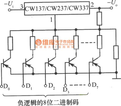
Negative logic 8-bit binary code。 (View)
View full Circuit Diagram | Comments | Reading(758)
Integrated voltage regulator with continuously adjustable voltage from zero circuit
Published:2011/3/28 3:51:00 Author:Joan | Keyword: Continuously adjustable , integrated voltage regulator
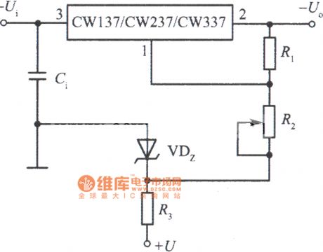
Above is Integrated voltage regulator with continuously adjustable voltage from zero circuit consisting of CW137. (View)
View full Circuit Diagram | Comments | Reading(619)
Constant current source circuit consisting of CW137
Published:2011/3/28 3:50:00 Author:Joan | Keyword: Constant current source

View full Circuit Diagram | Comments | Reading(546)
Integrated voltage regulator CW137 standard application circuit
Published:2011/3/28 3:49:00 Author:Joan | Keyword: Three-terminal adjustable , negative output voltage , integrated voltage regulator , standard application
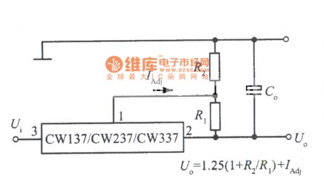
Above is Three-terminal adjustable negative output voltage integrated voltage regulator CW137 standard application circuit. (View)
View full Circuit Diagram | Comments | Reading(570)
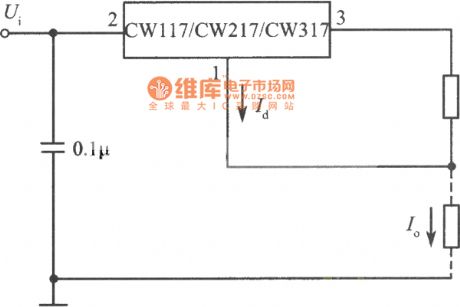
Standard constant current source circuit consisting of CW117
Published:2011/3/28 3:47:00 Author:Joan | Keyword: Standard constant current source
View full Circuit Diagram | Comments | Reading(652)
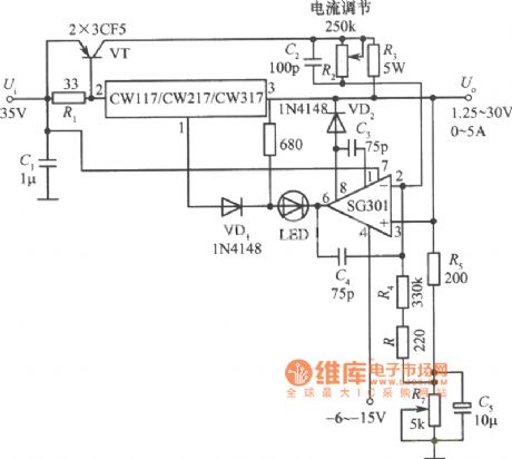
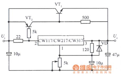
Constant voltage source / constant current source circuit consisting of CW117
Published:2011/3/28 3:43:00 Author:Joan | Keyword: Constant voltage source, constant current source
View full Circuit Diagram | Comments | Reading(1240)
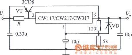
Extended current integrated voltage regulator with an external NPN transistor circuit
Published:2011/3/25 1:10:00 Author:Joan | Keyword: Extended current , integrated voltage regulator , NPN transistor
View full Circuit Diagram | Comments | Reading(665)
Extended current integrated voltage regulator with an external PNP transistor circuit
Published:2011/3/25 1:09:00 Author:Joan | Keyword: Extended current , integrated voltage regulator , PNP transistor
View full Circuit Diagram | Comments | Reading(628)
Input short-circuit protection and fixed negative output integrated voltage regulator circuit
Published:2011/3/25 0:40:00 Author:Joan | Keyword: Large capacitive load , input short-circuit protection , fixed negative output , integrated voltage regulator
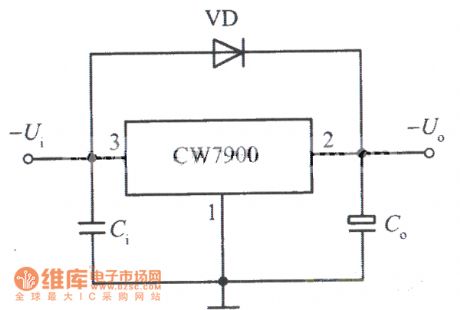
Above is Input short-circuit protection and fixed negative output integrated voltage regulator with Large capacitive load circuit. (View)
View full Circuit Diagram | Comments | Reading(761)
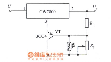
Light control integrated voltage regulator circuit 1
Published:2011/3/25 0:35:00 Author:Joan | Keyword: integrated voltage regulator , Light control
View full Circuit Diagram | Comments | Reading(535)
800W two-way dimmer control circuit
Published:2011/3/21 1:49:00 Author:Joan | Keyword: dimmer control
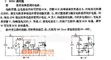
800W dimmer circuit:
The below figure is a typical dimmer circuit.
Circuit principle: the main circuit is a triac SCR. It controls SCR conduction angle to change the current through RL, so as to achieve dimming purpose. The trigger circuit is a single junction transistor phase-shift trigger. QL bridge rectifier provides synchronization power for the trigger circuit. the R1 reduced voltage, DW regulator provided synchronous voltage for the single-junction transistor, W and C1 form phase shift circuit.
When the synchronous power charges C1 to unijunction transistor V1 peak voltage, V1 turns on, C1 discharged current generates pulses in the T1 secondary, which triggers SCR turn on. Adjusted W can change the SCR conduction angle.
Pulse transformer winding: Wire around ferrite core 60 ~ 80T each with a diameter of 0.2mm magnet in the primary and secondary.
(View)
View full Circuit Diagram | Comments | Reading(970)
Infrared wireless alarm sensor circuit
Published:2011/3/21 1:28:00 Author:Joan | Keyword: Infrared sensor, wireless sensor, alarm sensor
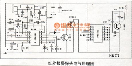
Infrared wireless alarm sensor circuit. (View)
View full Circuit Diagram | Comments | Reading(1007)
Jetta electromagnetic clutch, pressure switch, radiator fan, 2V motor circuit
Published:2011/3/23 1:35:00 Author:Joan | Keyword: Jetta , electromagnetic clutch, pressure switch, radiator fan, 2V motor
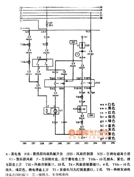
A-BatteryF18-Radiator fan thermal switchJ555-Fan ControllerN25-Air condition electromagnetic clutchV7-Radiator fanP-Main fuse box, located above the batteryT10b-10-hole plug, purple, in the top of the relay boxT10-Fan control port, 10 holesT4-Fan Controller Interface, 4-holeT10c-10-hole plug, orange, in the top of the relay boxT2-Engine and Headlight Harness Interface, 2 holesT8-The interface between the two engine wire harness7-Connection points in the car body wire harnessThe figure is Jetta electromagnetic clutch, pressure switch, radiator fan, 2V motor circuit. (View)
View full Circuit Diagram | Comments | Reading(1085)
Infrared micro-computer automatical pump fluid hardware design circuit
Published:2011/3/23 2:42:00 Author:Joan | Keyword: micro-computer , automatical pump fluid , Infrared pump fluid

The design uses a Microchip PIC16C54 microcontroller, selects GR40101 GD1611 infrared emitting diodes and silicon PIN photodiode as the infrared transmit and receive devices, chooses micro motors QDB-30-3.0 LCD driver as the pump. The system uses one-touch mode to complete suspension, setting the pump fluid volume and other functions.The circuit design uses power-saving mode with standby current less than 100μA, provides the necessary 500mA load current for micro-motor, and can monitor battery voltage, alarm when the battery is under voltage. System schematic is shown below.
In above figure, TX (infrared emission diode), R1, R5, Q4 constitute infrared emission circuit. Microcontroller port RA1 outputs certain frequency pulse to control transistor Q4 on or off, so as to control the transmit frequency of the infrared emission diode TX. MCU RA3 port provides power for the transmitter circuit for energy conservation. When RA1 port launchs pulse, RA3 port set high, firing circuit is power on. RX (infrared receiver), R2, R11, R12, R13, R16, Q6, C3 constitute infrared receiver circuit. RX receives infrared pulse, which is amplified by Q6 after being shaped.
Receiving circuit magnification must be strictly controlled to ensure the infrared reflection receive distance of about 10cm. Receiving circuit power is provided by the MCU port RB1. After the pulse launch, RB1 port sets high. R6, R7, R8, Q3 constitute battery voltage monitoring circuit. When the supply voltage drops to a certain value, Q3 cuts off, MCU port RB3 sets high, the circuit alarms for under-voltage. D2, D3, R9, R10, Q1, Q5 constitute the motor power supply circuit to provide the necessary 3V voltage and 500mA load current for the micro-motor. When needs to drive motor pump fluid, the microcontroller port RB2 output low voltage, Q emitter provides power supply for the motor. D1, C4, Q2, R3 constitute motor control circuit, it provides power supply for the motor first when pumps fluid, and then microcontroller port RA2 output high voltage to drive motor running. The LED is the work status indicator. The single function SW key, can set the pump fluid volume, pump fluid suspension, manual pump fluid and other functions. (View)
View full Circuit Diagram | Comments | Reading(1159)
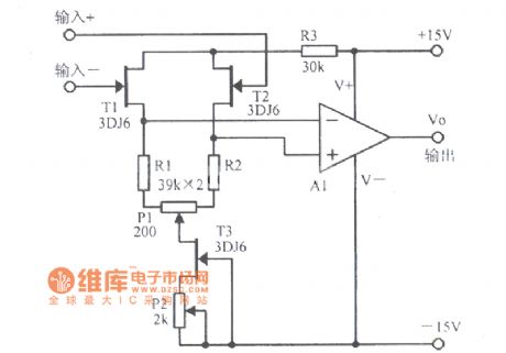
Increasing the input impedance Amplifier With FET Circuit Diagram
Published:2011/3/21 0:45:00 Author:Joan | Keyword: Amplifier, input impedance, FET
View full Circuit Diagram | Comments | Reading(740)
Infrared automatic faucet schematic
Published:2011/3/21 1:27:00 Author:Joan | Keyword: Infrared faucet, automatic faucet, automatic faucet
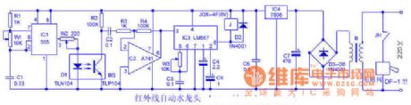
How it works:The circuit is shownas the figure. IC1 and W1, C1 and other components compose a 30 ~ 50KHz frequency pulse oscillator. It drives the infrared light-emitting diode D1 to send modulated infrared light. When someone close to the faucet for washing hands or hold water, a part of the the infrared ray emitted by the D1 which reflected back by the human body part is received by BG and then is amplified by op amp IC2 and then input to pin 3 of the audio decoder LM567. After decoding and dentifying it, the IC3 makes pin 8 output low. Relay J pulls in, normally open contact point JH connects to the solenoid valve power. Electromagnetic valve is opened, the faucet water automatically. When the human body leaves the faucet, BG lost infrared signal, then the circuit returns to the general state of waiting for work.
Debug: Cover up D1 and BG by iron sheet. Tunning W1, W3 can make the infrared transmitter and receiver of the same frequency. When the human body is close to the faucet, the solenoid valve can reliably act. Regulating W2 resistance can change the D1 emission current, then the circuit can control the effective action distance when the human body close to the faucet(ie, sensitivity). (View)
View full Circuit Diagram | Comments | Reading(3643)
Differential temperature measurement Circuit Diagram
Published:2011/3/21 0:52:00 Author:Joan | Keyword: temperature measurement, Differential temperature
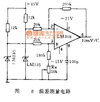
The temperature difference between two points is often measured in many situations. For example, in water pump fan design and other designs, the impeller shape is always detemined by the temperature difference between the entrance and exit. if the difference is small, it requires high precision phase resolution. Figure 8 shows a high sensitivity temperature measurement circuit with 100mV / ℃ sensitivity. The precision op amp LM308 ouput 10 times of the differential temperature voltage the two temperature sensors measured. The Op amp output will be 0 by adjust the Rw when the two sensors are in the same temperature.
(View)
View full Circuit Diagram | Comments | Reading(2835)
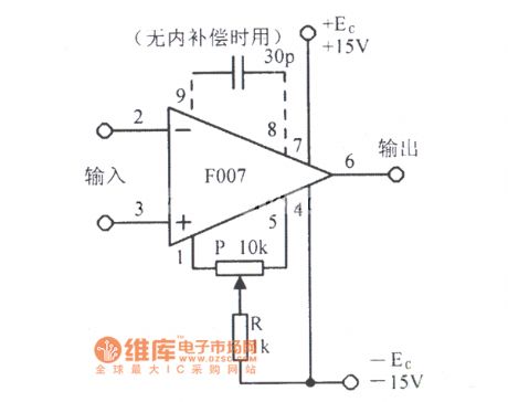
Integrated Amplifier F007 Basic Application Circuit Diagram
Published:2011/3/23 20:21:00 Author:Joan | Keyword: Integrated Amplifier, Basic Application
View full Circuit Diagram | Comments | Reading(577)
Infant sleep monitor
Published:2011/3/28 3:17:00 Author:Ecco | Keyword: Infant sleep monitors
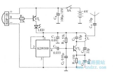
This circuit is composed of power switch circuit controlled by pyroelectric infrared detection module , analog music generating circuit and FM radio emission circuit component. (View)
View full Circuit Diagram | Comments | Reading(712)
| Pages:2198/2234 At 2021812182218321842185218621872188218921902191219221932194219521962197219821992200Under 20 |
Circuit Categories
power supply circuit
Amplifier Circuit
Basic Circuit
LED and Light Circuit
Sensor Circuit
Signal Processing
Electrical Equipment Circuit
Control Circuit
Remote Control Circuit
A/D-D/A Converter Circuit
Audio Circuit
Measuring and Test Circuit
Communication Circuit
Computer-Related Circuit
555 Circuit
Automotive Circuit
Repairing Circuit