
Circuit Diagram
Index 24
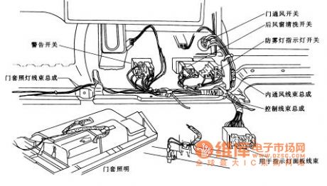
桑塔纳2000轿车的发动机室照明线束布置电路图
Published:2014/2/19 21:04:00 Author: | Keyword: 桑塔纳2000轿车的发动机室照明线束布置电路图,
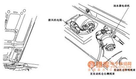
Santana 2000 car engine room as shown lighting wiring harness layout diagram (View)
View full Circuit Diagram | Comments | Reading(1940)
The basic principle of static switch circuit diagram
Published:2014/2/19 21:02:00 Author: | Keyword: The basic principle of static switch circuit diagram,
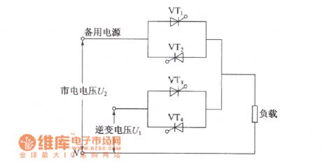
The effect of static switch: two ac power frequency and amplitude are just can work in parallel at the same time. When an ac power failure occurs, will produce a balance between the two power supply current, so that the change of two parallel power supply output voltage, affect the reliability of power supply. Static switch is used to cut off the power source of the failure of the output, achieve the inverter output and uninterrupted switch between the mains bypass output. For less than 2 kva on-line UPS power supply, the inverter output and mains bypass output q switch, USES fast relay as switching elements, mostly because of the switching time is only 2 ~ 5 ms, ms to fit the needs of communication equipment for power don't interrupt. For capacity in more than 2 kva UPS power supply, due to the relay working current increases, the switch time will increase to 80 ms to 120 ms, and snap relay instant sparks will produce high temperature and damage the contact, or often opened in electric arc is formed between the normally closed contacts and will have a instantaneous short circuit, two ac power, so relay used in switching is limited to small capacity of UPS power supply. Ac double contactor with interlock properties, although can control the output power larger UPS power supply, but the switch time has more than 10 milliseconds. (View)
View full Circuit Diagram | Comments | Reading(1003)
In line with the discriminator circuit diagram
Published:2014/2/19 21:00:00 Author: | Keyword: In line with the discriminator circuit diagram,
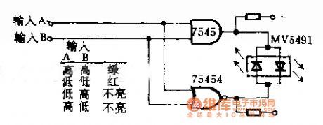
In line with the discriminator circuit diagram
(View)
View full Circuit Diagram | Comments | Reading(907)
Santana 2000 car engine room wiring harness layout diagram
Published:2014/2/19 20:36:00 Author: | Keyword: Santana 2000 car engine room wiring harness layout diagram,
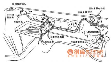
Santana 2000 car engine room as shown wiring harness layout diagram (View)
View full Circuit Diagram | Comments | Reading(1089)
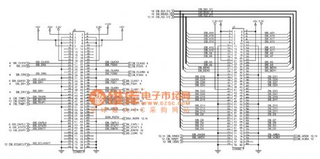
ICETEK C6711 - A principle in figure 10
Published:2014/2/19 20:35:00 Author: | Keyword: ICETEK C6711 - A principle in figure 10,
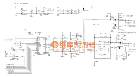
ICETEK - C6711 - A principle as shown in figure 10 (View)
View full Circuit Diagram | Comments | Reading(835)
Set the static switch type single phase transformation of UPS power main circuit frame diagram
Published:2014/2/19 20:32:00 Author: | Keyword: Set the static switch type single phase transformation of UPS power main circuit frame diagram,
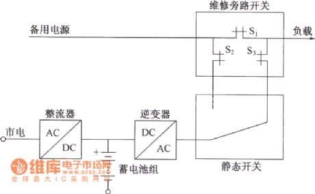
UPS power inverter based on combination can be divided into the transformation type and model, set up the static switch type single phase transformation of UPS power main circuit diagram as shown. The figure shows that when the mains is normal, for the inverter output as the main power supply load. In order to facilitate maintenance, set up a manual maintenance bypass switch, namely access to bypass switch S, closed, and then make the S2, S3 and static switch. Under standby power supply power to the load, the UPS system away from the bypass system, which can do maintenance of inverter, static switch. When the inverter as primary power supply, first close the static switch and the bypass switch S2, S3, and then disconnect S1. (View)
View full Circuit Diagram | Comments | Reading(1014)
The ladder wave inverter output three-phase transformer winding connection circuit diagram and the output voltage waveform
Published:2014/2/19 20:23:00 Author: | Keyword: The ladder wave inverter output three-phase transformer winding connection circuit diagram and the output voltage waveform,
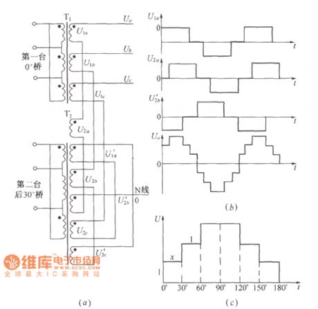
As shown in figure, (a) the ladder wave inverter for three-phase output transformer winding connection; (b) the output waveform. (View)
View full Circuit Diagram | Comments | Reading(2764)
Motor working condition sound and light warning circuit
Published:2014/2/19 19:56:00 Author:lynne | Keyword: Motor working condition sound and light warning circuit,
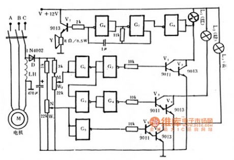
Motor working condition sound and light warning circuit shown in Figure:
(View)
View full Circuit Diagram | Comments | Reading(964)
Triac prolong the life of incandescent circuit
Published:2014/2/19 20:16:00 Author:lynne | Keyword: Triac prolong the life of incandescent circuit,
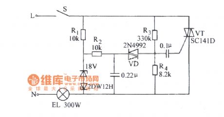
Triac prolong the life of incandescent circuit shown in Figure:
(View)
View full Circuit Diagram | Comments | Reading(1324)
Dongfeng Peugeot Citroen Picasso 2.0L sedan position lamp circuit
Published:2014/2/19 20:18:00 Author:lynne | Keyword: Dongfeng Peugeot Citroen Picasso 2.0L sedan position lamp circuit,
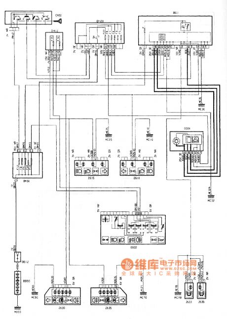
Dongfeng Peugeot Citroen Picasso 2.0L sedan position lamp circuit shown in Figure:
(View)
View full Circuit Diagram | Comments | Reading(978)
Smog alarm circuit
Published:2014/2/19 20:20:00 Author:lynne | Keyword: Smog alarm circuit,
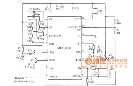
Smog alarm circuit shown in Figure:
(View)
View full Circuit Diagram | Comments | Reading(999)
Dongfeng Peugeot Citroen Picasso 2.0L sedan turn signal circuit
Published:2014/2/19 20:43:00 Author:lynne | Keyword: Dongfeng Peugeot Citroen Picasso 2.0L sedan turn signal circuit,
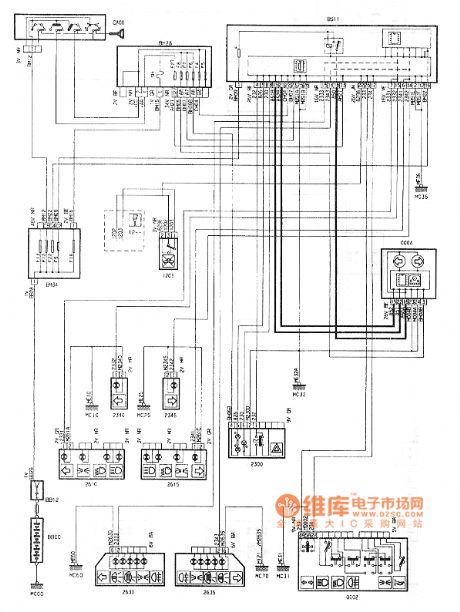
Dongfeng Peugeot Citroen Picasso 2.0L sedan turn signal circuit shown in Figure:
(View)
View full Circuit Diagram | Comments | Reading(816)
Full bridge inverter circuit full bridge inverter circuit diagram
Published:2014/2/18 21:52:00 Author: | Keyword: Full bridge inverter circuit full bridge inverter circuit diagram,
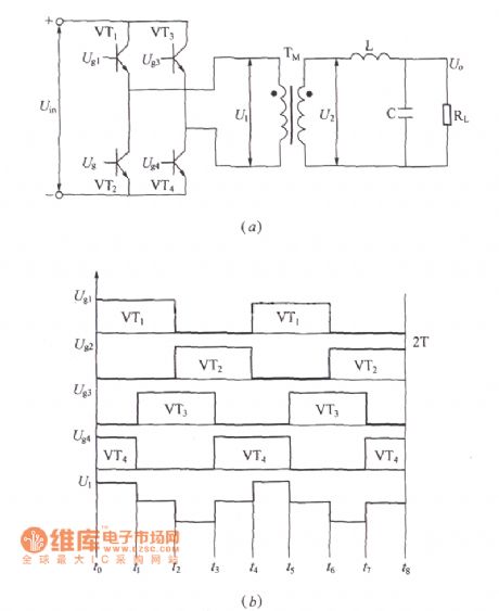
Single-phase inverter circuit is push-pull type, half bridge type and bridge type, among them, the full bridge inverter circuit for use in the most common. Single phase full bridge inverter circuit principle as shown in figure (a). (b) excitation signal and the output voltage waveform. (View)
View full Circuit Diagram | Comments | Reading(1684)
Santana 2000 car speed odometer sensor layout diagram
Published:2014/2/18 21:50:00 Author: | Keyword: Santana 2000 car speed odometer sensor layout diagram,

As shown santana 2000 car speed odometer sensor layout diagram (View)
View full Circuit Diagram | Comments | Reading(1861)
ICETEK C6711 -- A principle figure 11
Published:2014/2/18 21:49:00 Author: | Keyword: ICETEK C6711 -- A principle figure 11,
ICETEK - C6711 - A principle as shown in figure 11 (View)
View full Circuit Diagram | Comments | Reading(1016)
Make straight play three digital voltmeter circuit diagram
Published:2014/2/18 21:47:00 Author: | Keyword: Make straight play three digital voltmeter circuit diagram,
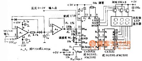
Make straight play three digital voltmeter circuit diagram
(View)
View full Circuit Diagram | Comments | Reading(1549)
Deformation of the half bridge converter principle of electric circuit diagram
Published:2014/2/18 21:46:00 Author: | Keyword: Deformation of the half bridge converter principle of electric circuit diagram,
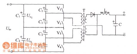
For high input, high power output, generally USES the way of circuit as shown. In the circuit, switching devices V1, V2, V3 and V4 as a group, both in series and can reduce the single pipe pressure values. In the practical application circuit switch device in the V1, V2, V3 and V4 can adopt double pipe or in parallel, can solve the problem of large current output. Common transformer can improve the utilization efficiency of transformer, and has the ability to resist imbalance. In series of half bridge circuit, power transformation V1, V2 and V3, V4 each maximum withstand voltage value of the switch tube is only ucs 1 or Uc2 value, if C1 = C2, the ucs 1 = Uc2 = Uin / 2 value, therefore can choose to reduce the pressure switch tube. Another V1, V2, V3 and V4 manifold can be used in parallel work, increasing the capacity of the output current; T can work on the positive and negative direction for transformer, greatly improve the efficiency of the transformer. In view of the above advantages, the circuit has been more widely used, especially in the occasion of high input voltage and high power output, its application is becoming more common. (View)
View full Circuit Diagram | Comments | Reading(916)
Santana 2000 car dashboard harness layout diagram
Published:2014/2/18 21:45:00 Author: | Keyword: Santana 2000 car dashboard harness layout diagram,
As shown santana 2000 car dashboard harness layout diagram (View)
View full Circuit Diagram | Comments | Reading(2078)
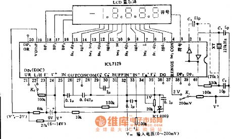
Four and a half LCD digital voltmeter circuit diagram
Published:2014/2/18 21:44:00 Author: | Keyword: Four and a half LCD digital voltmeter circuit diagram,

Four and a half LCD digital voltmeter circuit diagram
(View)
View full Circuit Diagram | Comments | Reading(1850)
Four and a half LED counting circuit diagram
Published:2014/2/18 21:41:00 Author: | Keyword: Four and a half LED counting circuit diagram,
Four and a half LED counting circuit diagram
(View)
View full Circuit Diagram | Comments | Reading(1471)
| Pages:24/2234 At 202122232425262728293031323334353637383940Under 20 |
Circuit Categories
power supply circuit
Amplifier Circuit
Basic Circuit
LED and Light Circuit
Sensor Circuit
Signal Processing
Electrical Equipment Circuit
Control Circuit
Remote Control Circuit
A/D-D/A Converter Circuit
Audio Circuit
Measuring and Test Circuit
Communication Circuit
Computer-Related Circuit
555 Circuit
Automotive Circuit
Repairing Circuit