
Circuit Diagram
Index 34
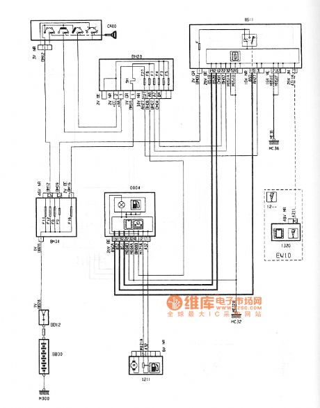
Dongfeng Peugeot Citroen Picasso 2.0L Sedan electric heating rear windshield automatic air conditioning circuit diagram
Published:2014/1/20 20:25:00 Author:lynne | Keyword: Dongfeng Peugeot Citroen Picasso 2.0L Sedan electric heating rear windshield automatic air conditioning circuit diagram,
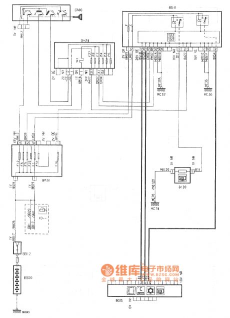
Dongfeng Peugeot Citroen Picasso 2.0L Sedan electric heating rear windshield automatic air conditioning circuit diagram shown in Figure:
(View)
View full Circuit Diagram | Comments | Reading(1007)
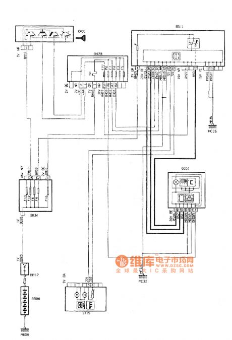
Dongfeng Peugeot Citroen Picasso 2.0L Sedan electric heating rear windshield circuit diagram
Published:2014/1/20 20:22:00 Author:lynne | Keyword: Dongfeng Peugeot Citroen Picasso 2.0L Sedan electric heating rear windshield circuit diagram,
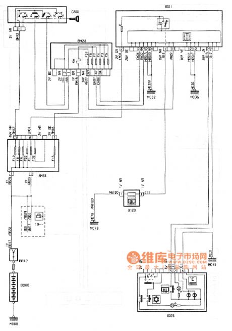
Dongfeng Peugeot Citroen Picasso 2.0L Sedan electric heating rear windshieldcircuit diagram shown in Figure:
(View)
View full Circuit Diagram | Comments | Reading(967)
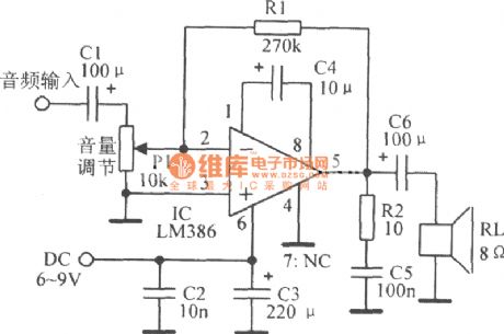
Composed of LM386 20 gain amplification circuit diagram
Published:2014/1/20 20:08:00 Author: | Keyword: Composed of LM386 20 gain amplification circuit diagram,
View full Circuit Diagram | Comments | Reading(1140)
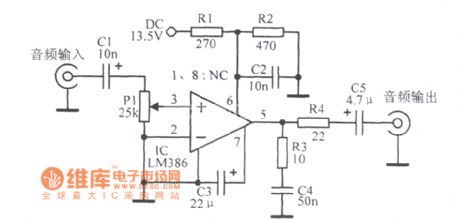
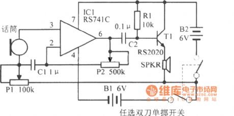
Made up of audio amplifier IC LM386 practical circuit diagram
Published:2014/1/20 20:07:00 Author: | Keyword: Made up of audio amplifier IC LM386 practical circuit diagram,
View full Circuit Diagram | Comments | Reading(1959)
General amplifier circuit diagram
Published:2014/1/20 20:06:00 Author: | Keyword: General amplifier circuit diagram,

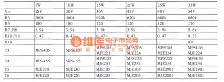
Parameter selection:
(View)
View full Circuit Diagram | Comments | Reading(2039)
High gain op amp transistor output circuit diagram
Published:2014/1/20 20:05:00 Author: | Keyword: High gain op amp transistor output circuit diagram,
View full Circuit Diagram | Comments | Reading(1110)
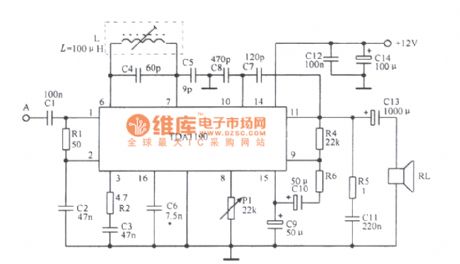
Composed of TDAll90 practical circuit diagram
Published:2014/1/20 20:04:00 Author: | Keyword: Composed of TDAll90 practical circuit diagram,
View full Circuit Diagram | Comments | Reading(904)
Composed of MCl351 practical circuit diagram
Published:2014/1/20 20:02:00 Author: | Keyword: Composed of MCl351 practical circuit diagram,
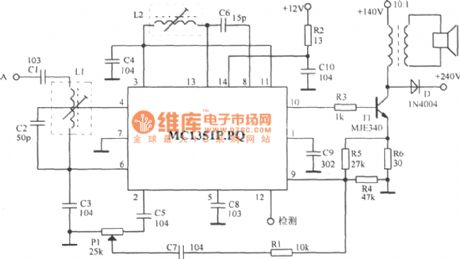
MCl351 containing limiting amplifier, phase shift converter, multiplier, low-pass filter and audio preamplifier circuit, etc. (View)
View full Circuit Diagram | Comments | Reading(829)
Audio frequency amplifier circuit diagram
Published:2014/1/20 20:01:00 Author: | Keyword: Audio frequency amplifier circuit diagram,
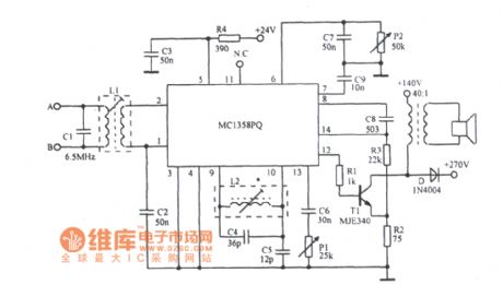
MCl358 frequency linear amplifier IC includes additional power regulators, limiters, and the audio electronic control attenuator driver circuit. (View)
View full Circuit Diagram | Comments | Reading(989)
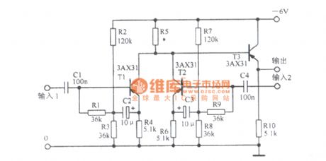
Bass modulation amplifier circuit diagram
Published:2014/1/20 19:59:00 Author: | Keyword: Bass modulation amplifier circuit diagram,
View full Circuit Diagram | Comments | Reading(1285)
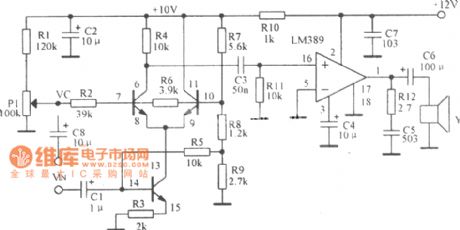
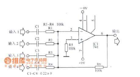
Mixing amplifier circuit diagram
Published:2014/1/20 19:58:00 Author: | Keyword: Mixing amplifier circuit diagram,
View full Circuit Diagram | Comments | Reading(1139)
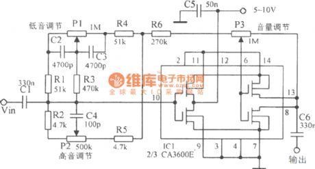
Audio power amplifier with high bass control circuit diagram
Published:2014/1/20 19:56:00 Author: | Keyword: Audio power amplifier with high bass control circuit diagram,
View full Circuit Diagram | Comments | Reading(1190)
Dongfeng Peugeot Citroen Picasso 2.0L sedan fuel gauge circuit
Published:2014/1/19 21:59:00 Author:lynne | Keyword: Dongfeng Peugeot Citroen Picasso 2.0L sedan fuel gauge circuit,
Dongfeng Peugeot Citroen Picasso 2.0L sedan fuel gauge circuit shown in Figure:
(View)
View full Circuit Diagram | Comments | Reading(921)
Dongfeng Peugeot Citroen Picasso 2.0L sedan digital clock outside temperature circuit
Published:2014/1/19 21:57:00 Author:lynne | Keyword: Dongfeng Peugeot Citroen Picasso 2.0L sedan digital clock outside temperature circuit,
Dongfeng Peugeot Citroen Picasso 2.0L sedan digital clock outside temperature circuit shown in Figure:
(View)
View full Circuit Diagram | Comments | Reading(759)
Lu lian intelligent remote alarm system electric schematic diagram
Published:2014/1/19 21:52:00 Author:lynne | Keyword: Lu lian intelligent remote alarm system electric schematic diagram,
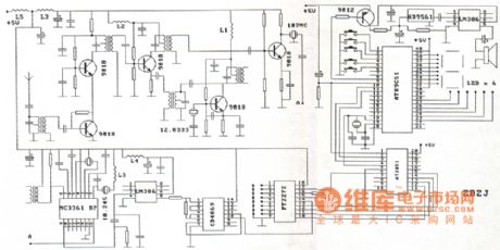
Lu lian intelligent remote alarm system electric schematic diagram as shown:
(View)
View full Circuit Diagram | Comments | Reading(1721)
Dongfeng Peugeot Citroen Picasso 2.0L sedan combination meter ECU circuit
Published:2014/1/19 21:49:00 Author:lynne | Keyword: Dongfeng Peugeot Citroen Picasso 2.0L sedan combination meter ECU circuit,
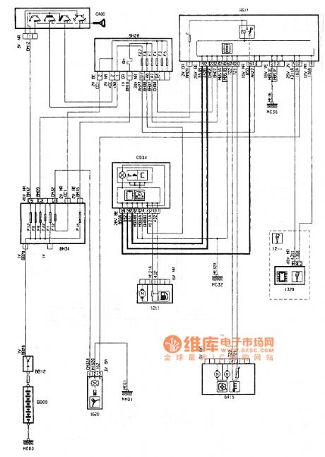
Dongfeng Peugeot Citroen Picasso 2.0L sedan combination meter ECU circuit shown in Figure:
(View)
View full Circuit Diagram | Comments | Reading(987)
Multi-channel burglar alarm circuit diagram
Published:2014/1/19 21:46:00 Author:lynne | Keyword: Multi-channel burglar alarm circuit diagram,
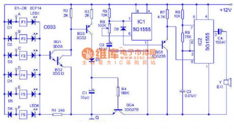
This alarm can be 6-way, from 0 to 30 km on the touch line in both sound and lighting for monitoring. Works in the following figure:Using 6 inverter C033 and light-emitting diodes (leds) as a touch alarm display. When the body contact (directly and/or wear gloves and indirect touch) when any one end in A ~ F, the end brings low potential, the inverter makes light-emitting tube LED display. At this moment, BG1 ~ BG4 conduction, C1 charging, acoustics part (IC1, IC2, etc.) begin to work. IC1, produce about 1 hz sawtooth wave by BG5 buffer to add to the IC2 modulation, IC1 oscillation frequency from low to high, the speaker sends out the similar public security police car alarm.
Use installation should pay attention to the Q end reliable to use A wire from the earth, A ~ F side respectively with bare copper wire to the surveillance, fixed place need porcelain insulation, at the same time pay attention to the rain, water, etc. Between cause and to form A low impedance. The alarm sensitivity is extremely high, standing on a chair touch wires can also call the police, the human body to leave after the all-clear to delay a few seconds. Power supply adopts 8 batteries. Adjust the R6 can change the tone. (View)
View full Circuit Diagram | Comments | Reading(2212)
Audio mixing amplifier circuit diagram
Published:2014/1/16 22:44:00 Author: | Keyword: Audio mixing amplifier circuit diagram,
View full Circuit Diagram | Comments | Reading(1227)
Santana 2000 gsi type car fog lamps, reversing lamp, license plate lamp, glove box lights, the speed sensor circuit diagram
Published:2014/1/16 22:34:00 Author: | Keyword: Santana 2000 gsi type car fog lamps, reversing lamp, license plate lamp, glove box lights, the speed sensor circuit diagram,
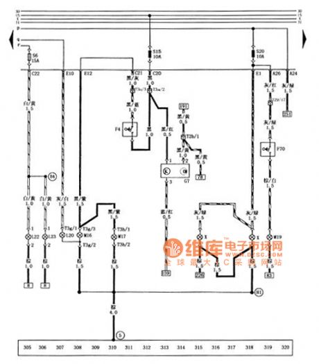
Figure of santana 2000 gsi saloon car fog lamps, reversing lamp, license plate lamp, glove box lights, the speed sensor circuit diagram
F4 - reversing lamp switch F70 - glove box light contact switch after the G7 - speed sensor L20 - fog lamps L22 - left front fog lamps L23 - right front fog lamps M16 - left back light M17 - right back light M19 - glove box lights S6 - front fog lamps fuse (15 a) S15 - reversing light fuse (10 a), speed sensor s20-40 lamp and glove box lighting the fuse (10 a) T2b - engine wiring harness and dashboard wiring harness connector (2 needle, on the left back light) T3a - the engine wiring harness and headlamps wiring harness connector (3 needles, behind the central circuit board) T3g - tail wire connected to the left back light plug (3 needles, on the left back light) T3h - tail wire connected to the right back light plug (3 needles, on the right back light) T29 - dashboard harness and dashboard switch wiring harness connector (29 needle, below the combination instrument) X - license plate lamp (5) - ground () on the circuit board on the right side of star grounding claw - the positive connections (within the headlamps harness) - grounding cables (within the tail wire) (View)
View full Circuit Diagram | Comments | Reading(1107)
Practical tones preamp circuit diagram
Published:2014/1/16 21:52:00 Author: | Keyword: Practical tones preamp circuit diagram, LM1036
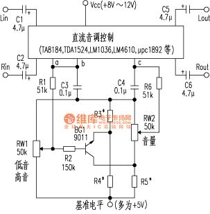
The core parts of the circuit by a dc tone control IC, a NPN transistor, and four resistors common enough. Other components are used in the dc tone control IC itself needs to peripheral components. Most dc tone control IC has himself to dc tone control circuit provides a reference level (mostly + 5 v), but mu PC1892 dc tone control IC, such as exception, must by external with + 5 v dc reference level. Figure 1 for this function circuit schematic diagram, figure 2 as an example.
Component parameter setting: as high and low adjusting potentiometer RW1 is in not ascend, BG1 should be ended, no influence of volume at this time. As high and low adjusting potentiometer RW1 from start to ascend, and finally achieve maximum lifting capacity + 12 db, BG1 by the globe into linear workspace, and then further into conducting state completely, leading to add on the volume potentiometer dc level to reduce the dc tone control IC output signal amplitude attenuation 12 db accordingly. Therefore, the circuit of R3, R4, R5 three selected tones of dc resistance and the associated control IC internal parameters. For example chooses dc tone control IC for the NS company LM1036 or LM1046 model, its resistance respectively choose = 22 k Ω R3 and R4 Ω Ω, R5 = 36 k = 5.6 k.
As shown practical tones preamp circuit diagram
(View)
View full Circuit Diagram | Comments | Reading(1549)
| Pages:34/2234 At 202122232425262728293031323334353637383940Under 20 |
Circuit Categories
power supply circuit
Amplifier Circuit
Basic Circuit
LED and Light Circuit
Sensor Circuit
Signal Processing
Electrical Equipment Circuit
Control Circuit
Remote Control Circuit
A/D-D/A Converter Circuit
Audio Circuit
Measuring and Test Circuit
Communication Circuit
Computer-Related Circuit
555 Circuit
Automotive Circuit
Repairing Circuit