
Circuit Diagram
Index 20
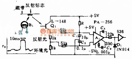
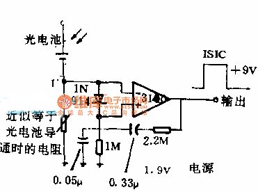
Electro-optical distance receiver circuit diagram
Published:2014/2/27 20:11:00 Author: | Keyword: Electro-optical distance receiver circuit diagram,
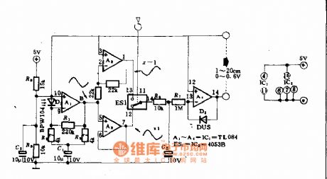
Electro-optical distance receiver circuit diagram (View)
View full Circuit Diagram | Comments | Reading(1609)
Based on the passive LM324 human body infrared sensor switch circuit
Published:2014/2/26 20:48:00 Author:lynne | Keyword: Based on the passive LM324 human body infrared sensor switch circuit,
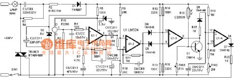
Infrared alarm switch using the most popular PIR human pyroelectric sensor for signal detector, high sensitivity, detection range up to 10 meters above its depression angles up to 86 °, horizontal viewing angle up to 120 °. It is only due to the release of the body, the specific wavelengths of infrared light sensitive, and thus erroneous operation minimal.
When someone with 0.3 ~ 3Hz frequency activity, PIR sensor can be induced in weak signal in the detection area by U1-1, U1-2 levels amplified from U1 (7) output of 0.5 to 5.5 feet V strong signal. D4, D5, R12 ~ R15 and U1-3 consisting of dual-threshold comparator, because the signal voltage induced PIR can be positive or negative, so U1 (7) pin output voltage can be positive or negative (in terms of the center voltage of 3V ). When the output voltage reaches 4.1V or more, through D4 applied to U1 (10) pin voltage is higher than (9) pin voltage (3.3V), so U1 (8) pin output high potential; And when U1 (7 ) when the pin output is below potential 2V, then U1 (voltage 9) pin will drop to 2.7V or less through D2, U1 (8) feet high potential output. Usually when there is no signal, because U1 (9) feet above the potential 3.3V (10) feet (2.7V), so (8) feet no output. When the PIR signal is received (8) feet on certain high potential output through D6, R17 to C9 charge, so U1 (12) feet higher than the potential (13) feet, which (14) feet high potential trigger bidirectional output thyristor conduction, lit the lamp. The stored energy due C8 through R19, RW2 discharge takes about two minutes, so within this 2 minutes light stays lit. When the voltage is lower than C9 (13) pin voltage (1V), the (14) feet no output, SCR turn off lights automatically turn off. CDS photoresistor composition and light control circuit transistor Q1, etc., during the day due to a small photosensitive resistor (10KΩ or less), the transistor Q1 saturated conduction, the U1 (8) feet clamped to about 0.3V, so regardless of whether the induction signal, SCR can not be turned on, the lamp can not be lit; night, due to larger photosensitive resistor to a few megohms, the transistor Q1 is turned off, U1 (8) feet no longer subject to the clamp, once receiving PIR signal, (8) feet immediately output high, the thyristor, the lamp is lit. (View)
View full Circuit Diagram | Comments | Reading(6012)
Dongfeng Peugeot Citroen Picasso 2.0L sedan deputy air conditioning circuit
Published:2014/2/26 20:36:00 Author:lynne | Keyword: Dongfeng Peugeot Citroen Picasso 2.0L sedan deputy air conditioning circuit,
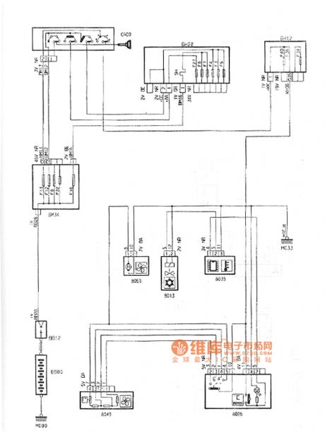
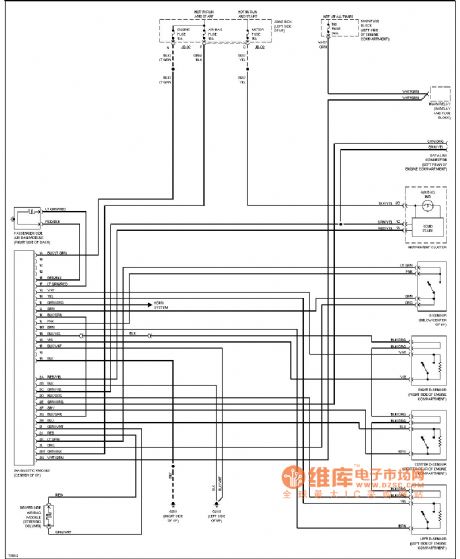
Dongfeng Peugeot Citroen Picasso 2.0L sedan deputy air conditioning circuit shown in Figure:
(View)
View full Circuit Diagram | Comments | Reading(1309)
Dongfeng Peugeot Citroen Picasso 2.0L sedan airbag seatbelt pre-tensioners circuit
Published:2014/2/26 20:38:00 Author:lynne | Keyword: Dongfeng Peugeot Citroen Picasso 2.0L sedan airbag seatbelt pre-tensioners circuit,
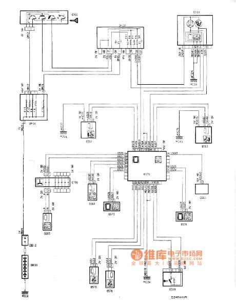
Dongfeng Peugeot Citroen Picasso 2.0L sedan airbag seatbelt pre-tensioners circuit shown in Figure:
(View)
View full Circuit Diagram | Comments | Reading(1713)
LM324 manufactured using low-cost PIR switch circuit diagram
Published:2014/2/26 20:43:00 Author:lynne | Keyword: LM324 manufactured using low-cost PIR switch circuit diagram,
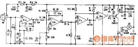
LM324 manufactured using low-cost PIR switch circuit diagram shown in Fig.:
Human pyroelectric infrared detection portion , mainly by the Fresnel lens and pyroelectric infrared sensors, four operational amplifier (LM324) and other components. When the range of the human body into the sensor monitoring , infrared energy lens focused into the low- pass amplifier noninverting IClA , C1, C2, C4 is a high frequency filter capacitor , C3 , and C5 infrared channel low-frequency AC signal . ICIB for the inverting amplifier by R5, R6 and the partial pressure of the noninverting terminal of the bias IClB 1 / 2 Supply voltage to amplify the AC signal , C7 is a high frequency filter capacitor, the two amplifier R3, R2, R8 , R4 determine the amplification gain . IClC composition comparator , ⑩ feet, through R10, R11 divider setting a reference voltage of about 3.9V , the reference voltage is also at the same time as the delay circuit IClD monostable trigger threshold level , 1CIC the comparison voltage signal ⑨ pin , in the photosensitive resistor RG acquired by IClB output through R9 , daytime RG by light , resistance ≤ 10kΩ, IClB high signal output by R9, RG partial pressure is still lower than IClC noninverting terminal level , IClC high power output flat , D1 reverse bias cut . IClD monostable circuit without trigger signal output high , SCR are off, the lamp is not lit . RG no light at night , its resistance ≥ 1MΩ, so IClC output low , D1 is turned on C9 discharges , IClD output low, the lamp is powered light. In the human left , ⑧ feet and high recovery , D1 and off, the power of C9 recharged by W1 , by the delay , when the voltage is higher than C9 ⑥ foot 3.9V, and a single flip -flop circuit IClD output high , lights off. Triac drive circuit triggered by BG SCR, can trigger more reliable. (View)
View full Circuit Diagram | Comments | Reading(10435)
CASPER TM-5154HY type multi-frequency color monitor power supply circuit
Published:2014/2/26 20:41:00 Author:lynne | Keyword: CASPER TM-5154HY type multi-frequency color monitor power supply circuit,
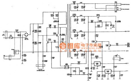
CASPER TM-5154HY type multi-frequency color monitor power supply circuit shown in Figure:
(View)
View full Circuit Diagram | Comments | Reading(1577)
Electro-optical distance transmitter circuit diagram
Published:2014/2/26 20:31:00 Author: | Keyword: Electro-optical distance transmitter circuit diagram,

Electro-optical distance transmitter circuit diagram
(View)
View full Circuit Diagram | Comments | Reading(1494)
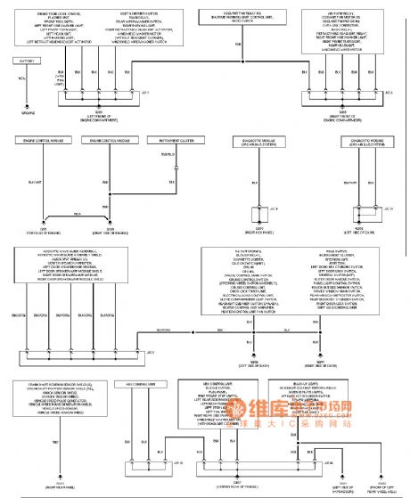
Mazda safety air bag circuit diagram
Published:2014/2/26 20:30:00 Author: | Keyword: Mazda safety air bag circuit diagram,
Mazda airbag circuit diagram as shown (View)
View full Circuit Diagram | Comments | Reading(1455)
Mazda air conditioning circuit diagram
Published:2014/2/26 20:28:00 Author: | Keyword: Mazda air conditioning circuit diagram,
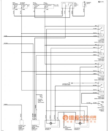
Mazda air conditioning circuit diagram as shown (View)
View full Circuit Diagram | Comments | Reading(1676)
Mazda security circuit diagram
Published:2014/2/26 20:27:00 Author: | Keyword: Mazda security circuit diagram,
Mazda anti-theft circuit diagram as shown (View)
View full Circuit Diagram | Comments | Reading(1252)
Mazda mist eliminator circuit diagram
Published:2014/2/26 20:23:00 Author: | Keyword: Mazda mist eliminator circuit diagram,
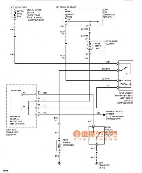
A circuit diagram as shown Mazda demister (View)
View full Circuit Diagram | Comments | Reading(1336)
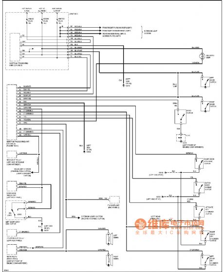
Mazda external modulation circuit diagram
Published:2014/2/26 20:22:00 Author: | Keyword: Mazda external modulation circuit diagram,
Mazda external light circuit diagram as shown (View)
View full Circuit Diagram | Comments | Reading(1245)
Tape fore and aft detector circuit diagram
Published:2014/2/26 20:21:00 Author: | Keyword: Tape fore and aft detector circuit diagram,
Tape fore and aft detector circuit diagram
(View)
View full Circuit Diagram | Comments | Reading(2124)
The light change detection circuit diagram
Published:2014/2/26 20:20:00 Author: | Keyword: The light change detection circuit diagram,
The light change detection circuit diagram
(View)
View full Circuit Diagram | Comments | Reading(2307)
Mazda iron distribution circuit diagram
Published:2014/2/26 20:19:00 Author: | Keyword: Mazda iron distribution circuit diagram,
Mazda take iron distribution circuit diagram as shown (View)
View full Circuit Diagram | Comments | Reading(1254)
To hear type light detector circuit diagram
Published:2014/2/26 20:18:00 Author: | Keyword: To hear type light detector circuit diagram,
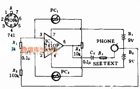
To hear type light detector circuit diagram
(View)
View full Circuit Diagram | Comments | Reading(1231)
Pulse frequency detection circuit diagram
Published:2014/2/25 21:19:00 Author: | Keyword: Pulse frequency detection circuit diagram,
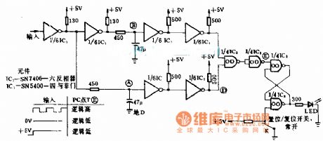
Pulse frequency detection circuit diagram
(View)
View full Circuit Diagram | Comments | Reading(2439)
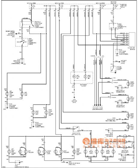
Mazda headlight circuit diagram (no DRL)
Published:2014/2/25 21:18:00 Author: | Keyword: Mazda headlight circuit diagram (no DRL),
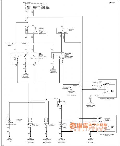
Mazda headlamps circuit diagram as shown (no DRL) (View)
View full Circuit Diagram | Comments | Reading(1418)
Mazda trumpet circuit diagram
Published:2014/2/25 21:17:00 Author: | Keyword: Mazda trumpet circuit diagram,
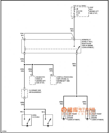
Mazda speakers circuit diagram as shown (View)
View full Circuit Diagram | Comments | Reading(1195)
Mazda car lamp circuit diagram
Published:2014/2/25 21:16:00 Author: | Keyword: Mazda car lamp circuit diagram,
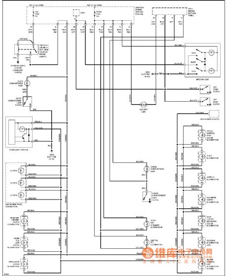
Mazda car lamp circuit diagram as shown (View)
View full Circuit Diagram | Comments | Reading(1393)
| Pages:20/2234 1234567891011121314151617181920Under 20 |
Circuit Categories
power supply circuit
Amplifier Circuit
Basic Circuit
LED and Light Circuit
Sensor Circuit
Signal Processing
Electrical Equipment Circuit
Control Circuit
Remote Control Circuit
A/D-D/A Converter Circuit
Audio Circuit
Measuring and Test Circuit
Communication Circuit
Computer-Related Circuit
555 Circuit
Automotive Circuit
Repairing Circuit