
Circuit Diagram
Index 6
Use full adder of four addition operation circuit diagram
Published:2014/4/24 21:08:00 Author:lynne | Keyword: Use full adder of four addition operation circuit diagram
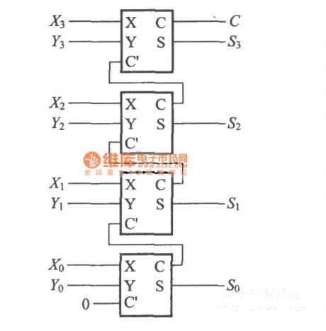
Use full adder of four addition operation circuit diagram shown as follow:
(View)
View full Circuit Diagram | Comments | Reading(2189)
Use the OR circuit, composed of diodes and resistors C = A + B circuit diagram
Published:2014/4/24 21:07:00 Author:lynne | Keyword: Use the OR circuit, composed of diodes and resistors C = A + B circuit diagram
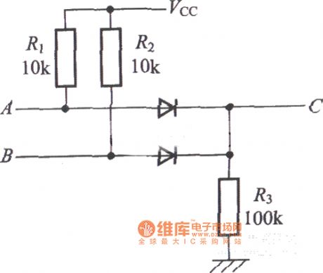
Use the OR circuit, composed of diodes and resistors C = A + B circuit diagram as shown:
(View)
View full Circuit Diagram | Comments | Reading(2079)
Four addition and subtraction operation circuit diagram
Published:2014/4/24 21:06:00 Author:lynne | Keyword: Four addition and subtraction operation circuit diagram
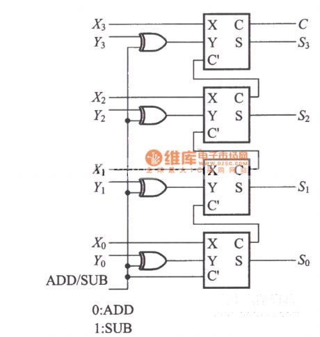
Four addition and subtraction operation circuit diagram shown as follow:
(View)
View full Circuit Diagram | Comments | Reading(2536)
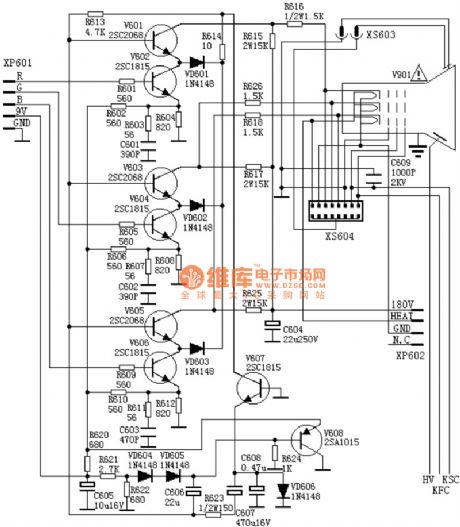
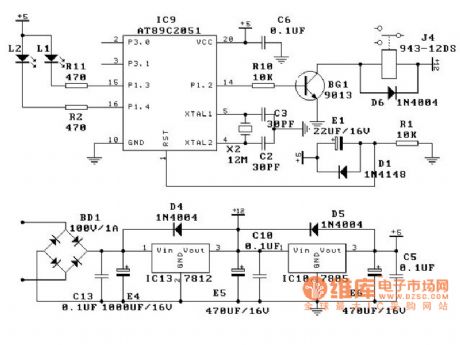
The TDA MCU power supply (A4) circuit diagram
Published:2014/4/24 21:04:00 Author:lynne | Keyword: The TDA MCU power supply (A4) circuit diagram

The TDA MCU power supply (A4) circuit diagram shown as follow:
(View)
View full Circuit Diagram | Comments | Reading(12467)
Video amplifier circuit board diagram
Published:2014/4/24 21:01:00 Author:lynne | Keyword: Video amplifier board circuit diagram
Video amplifier circuit board diagram as shown:
(View)
View full Circuit Diagram | Comments | Reading(2066)
Air flow detection circuit diagram
Published:2014/4/23 20:07:00 Author:lynne | Keyword: Air flow detection circuit diagram
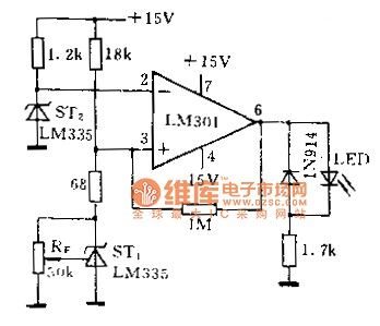
Figure LM335 work is the use of self-heating effects to detect the flow of gas. ST1 placed in still air, lower operating current of approximately 1mA. ST2 placed in the external environment, the operating current is large, about 10mA. ST3 operating current is large, and in the air does not flow from the heat generated during its rise above STl temperature rise, so LM301 comparator inverting input voltage is higher than the non-inverting input voltage. Output is low. When the external ambient air flow, the heat generated ST2 continuously taken away to the surrounding air, so the temperature rise caused by thermal effects from reduced. And then STl in still air, heat transfer is very slow, so the self-heating effects caused by the rise in temperature is greater than ST2, the LM301 comparator output goes high, driven LED lights alarm. By Rp alarm point can be set air flow rate.
(View)
View full Circuit Diagram | Comments | Reading(2326)
Praevia integrated amplifier infrared reception circuit diagram
Published:2014/4/23 20:10:00 Author:lynne | Keyword: Praevia integrated amplifier infrared reception circuit diagram
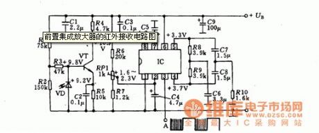
Praevia integrated amplifier infrared reception circuit diagram shown as follow:
(View)
View full Circuit Diagram | Comments | Reading(1746)
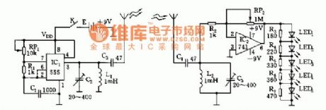
Using optical emission components detection of small displacement circuit diagram
Published:2014/4/23 20:11:00 Author:lynne | Keyword: Using optical emission components detection of small displacement circuit diagram
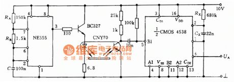
Figure oscillating signal generated by the base when the circuit 555 by emitting diode emitting element and a light guide phototransistor added 4538 plastic flip-resonant oscillator output once have tiny displacement of the reflected light intensity changes, multivibrator device will flip the output signal UA changes can be detected from the surface of the small displacement. Guiding light emitting element as shown in Figure small displacement detection circuit diagram:
(View)
View full Circuit Diagram | Comments | Reading(1906)
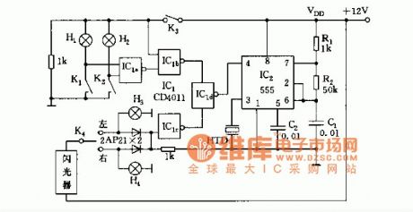
The bidirectional thyristor control for automatic nighttime lighting circuit diagram
Published:2014/4/23 20:17:00 Author:lynne | Keyword: The bidirectional thyristor control for automatic nighttime lighting circuit diagram
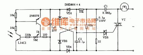
Illustrates the use of the circuit shown in the illuminance sensor as a phototransistor. During the day when the great illumination, phototransistor L14C1 conduction. Diode VD3 also conducting, the capacitor C2 drop to zero, the two-way and two-way thyristor trigger tube VD5 VT are not turned on, the lamp is not lit. Conversely, night L14C1 not conducting, there are so ST4 and C2 voltage VT conduction, the lamp will automatically light up.
(View)
View full Circuit Diagram | Comments | Reading(1999)
SONY G3F-K power circuit diagram
Published:2014/4/23 20:18:00 Author:lynne | Keyword: SONY G3F-K power circuit diagram, SONY G3F-K

SONY G3F-K power circuit diagram shown as follow:
(View)
View full Circuit Diagram | Comments | Reading(5546)
Soft decoding circuit diagram
Published:2014/4/22 21:19:00 Author:lynne | Keyword: Soft decoding circuit diagram
Soft decoding circuit diagram as shown:
(View)
View full Circuit Diagram | Comments | Reading(1906)
The doorbell circuit diagram
Published:2014/4/22 21:20:00 Author:lynne | Keyword: The doorbell circuit diagram

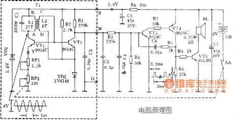
The doorbell circuit diagram shown as follow:
(View)
View full Circuit Diagram | Comments | Reading(2068)
Auto device circuit diagram
Published:2014/4/22 21:21:00 Author:lynne | Keyword: Auto device circuit diagram
Auto device circuit diagram shown as follow:
(View)
View full Circuit Diagram | Comments | Reading(5397)
Cycle timer circuit diagram
Published:2014/4/22 21:22:00 Author:lynne | Keyword: Cycle timer circuit diagram
Cycle timer circuit diagram as shown:
(View)
View full Circuit Diagram | Comments | Reading(3073)
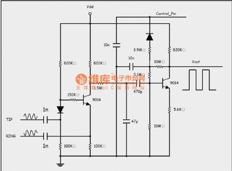
The car alarm circuit diagram
Published:2014/4/22 21:24:00 Author:lynne | Keyword: The car alarm circuit diagram
The car alarm circuit diagram shown as follow:
(View)
View full Circuit Diagram | Comments | Reading(2888)
Ethernet interface circuit diagram
Published:2014/4/21 20:23:00 Author:lynne | Keyword: Ethernet interface circuit diagram
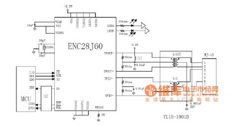
Ethernet interface circuit diagram shown as follow:
(View)
View full Circuit Diagram | Comments | Reading(2330)
Ethernet interface circuit diagram- IP101 Network
Published:2014/4/21 20:20:00 Author:lynne | Keyword: Ethernet interface circuit diagram- IP101 Network, IP101
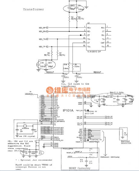
Ethernet interface circuit diagram- IP101 Network as shown:
(View)
View full Circuit Diagram | Comments | Reading(2596)
Pyroelectric infrared control IC S9803 circuit diagram
Published:2014/4/21 20:18:00 Author:lynne | Keyword: Pyroelectric infrared control IC S9803 circuit diagram, S9803

Pyroelectric infrared sensor for its anti-interference, high detection sensitivity, wide humidity range, etc. are used in the Pan-theft alarm, industrial and production of automatic doors, sensor lights, automatic valve and so on.
>
>
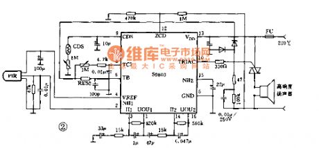
>S9803 is an integrated circuit designed for pyroelectric infrared sensor supporting the design, the use of CMOS technology. With high performance, consistency, and the external circuit is simple to install and easy to test. Similar products is more complete functional devices. S9803 is a prominent feature: High (1) sensitivity, built-in two-stage amplifier circuit and the gain can be transported humidity compensation circuit. This circuit can suppress infrared interference as warm air stream generated by the false alarm rate, the detection distance of 10m or more. [2) Control time is adjustable. (3) to drive the output thyristors or relays. (4) built-in regulator 3.1V. (5) External CDS sensor. Daytime suppress output. (6) Operating Voltage 4.0 - 5.5V. Current 1mA. (7) For AC power supply control circuit design zero crossing detection and control, so that the load on and off the accused are at the zero crossing of the AC. This not only reduced the impact of the load current, while also eliminating the interference of the power switching device. Reduce pollution power beam. S9803 is the oscillator, counter, PIP detection, signal amplification, clock, zero-crossing detection, temperature compensation, and output control circuit.
> (View)
View full Circuit Diagram | Comments | Reading(1690)
S9803 typical application circuit diagram
Published:2014/4/21 20:04:00 Author:lynne | Keyword: S9803 typical application circuit diagram, S9803
S9803 typical application circuit diagram shown as follow:
(View)
View full Circuit Diagram | Comments | Reading(1749)
MD-898K metal detector schematic circuit diagram
Published:2014/4/21 19:55:00 Author:lynne | Keyword: MD-898K metal detector schematic circuit diagram, MD-898K
MD-898K metal detector schematic circuit diagram shown as follow:
(View)
View full Circuit Diagram | Comments | Reading(2968)
| Pages:6/2234 1234567891011121314151617181920Under 20 |
Circuit Categories
power supply circuit
Amplifier Circuit
Basic Circuit
LED and Light Circuit
Sensor Circuit
Signal Processing
Electrical Equipment Circuit
Control Circuit
Remote Control Circuit
A/D-D/A Converter Circuit
Audio Circuit
Measuring and Test Circuit
Communication Circuit
Computer-Related Circuit
555 Circuit
Automotive Circuit
Repairing Circuit