
Circuit Diagram
Index 17
Audi circuitry C15
Published:2014/3/4 20:37:00 Author: | Keyword: Audi circuitry C15,
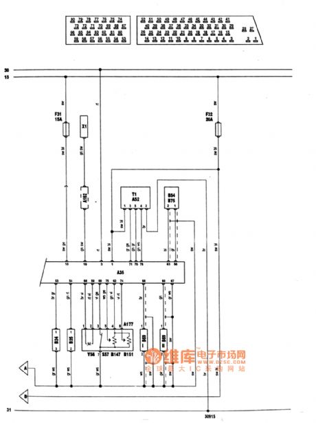
Audi circuit diagram as shown C15 (View)
View full Circuit Diagram | Comments | Reading(1427)
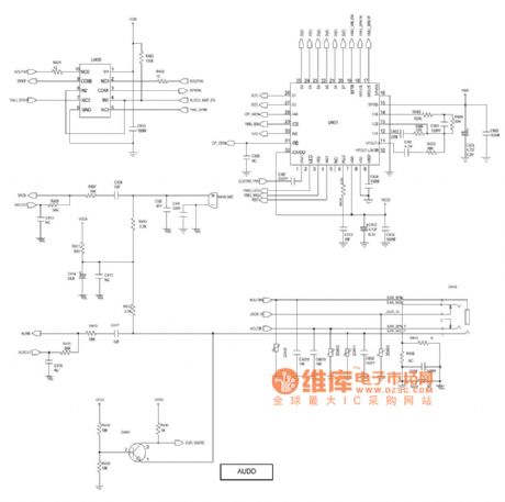
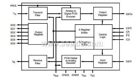
SGH - P408 troubleshooting and circuit principle diagram _07
Published:2014/3/4 20:35:00 Author: | Keyword: SGH - P408 troubleshooting and circuit principle diagram _07,
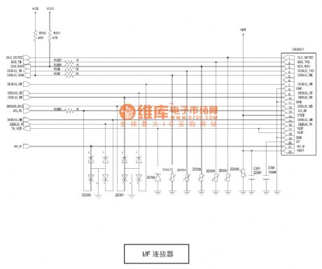
SGH as shown - P408 troubleshooting and circuit principle diagram _07 (View)
View full Circuit Diagram | Comments | Reading(1657)
Universal jinbei Portland auto electric Windows after the circuit diagram
Published:2014/3/4 20:32:00 Author: | Keyword: Universal jinbei Portland auto electric Windows after the circuit diagram,
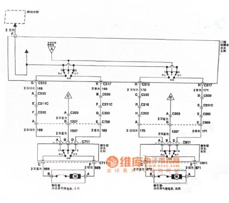
As shown in this universal jinbei Portland auto electric Windows after the circuit diagram (View)
View full Circuit Diagram | Comments | Reading(1316)
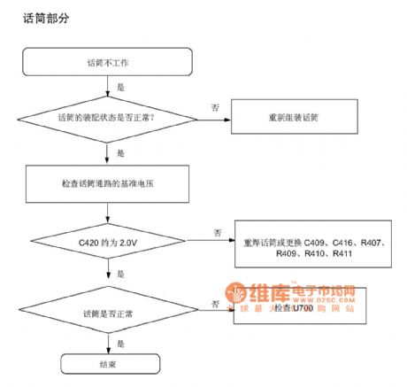
SGH - P408 troubleshooting and circuit principle diagram _08
Published:2014/3/4 20:26:00 Author: | Keyword: SGH - P408 troubleshooting and circuit principle diagram _08,
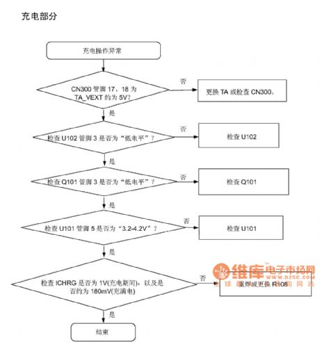
SGH as shown - P408 troubleshooting and circuit principle diagram _08 (View)
View full Circuit Diagram | Comments | Reading(1600)
Mazda cruise control circuit diagram
Published:2014/3/4 20:23:00 Author: | Keyword: Mazda cruise control circuit diagram,
Mazda cruise control circuit diagram as shown (View)
View full Circuit Diagram | Comments | Reading(1622)
SGH - P408 troubleshooting and circuit principle diagram _09
Published:2014/3/4 20:22:00 Author: | Keyword: SGH - P408 troubleshooting and circuit principle diagram _09,
SGH as shown - P408 troubleshooting and circuit principle diagram _09 (View)
View full Circuit Diagram | Comments | Reading(1763)
SGH - P408 troubleshooting and circuit principle diagram _10
Published:2014/3/4 20:16:00 Author: | Keyword: SGH - P408 troubleshooting and circuit principle diagram _10,
SGH as shown - P408 troubleshooting and circuit principle diagram _10 (View)
View full Circuit Diagram | Comments | Reading(1647)
Automatic battery charger circuit diagram
Published:2014/3/4 20:18:00 Author:lynne | Keyword: Automatic battery charger circuit diagram,
As shown in Fig automatic battery charger circuit diagram:
(View)
View full Circuit Diagram | Comments | Reading(2486)
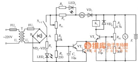
With SK-IV voice sounding music with automatic lighting circuit diagram
Published:2014/3/4 20:17:00 Author:lynne | Keyword: With SK-IV voice sounding music with automatic lighting circuit diagram,

Circuit is shown, comprising a transducer microphone, voice circuit, thyristor control circuit, and the circuit share the music sound buck rectifier circuit. BH-SK-IV is the core component of the circuit.
(View)
View full Circuit Diagram | Comments | Reading(2173)
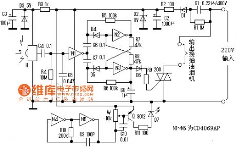
Sound and light dual control electric appliance switches and sockets circuit diagram
Published:2014/3/4 20:15:00 Author:lynne | Keyword: Sound and light dual control electric appliance switches and sockets circuit diagram,
Circuit as shown, it is by the sound transducer sensing switch / electrical, light control switch, thyristor control circuit, vocal music buck rectifier circuit and the AC circuit.
(View)
View full Circuit Diagram | Comments | Reading(1669)
Santana 2000 anti-theft system circuit diagram
Published:2014/3/4 19:57:00 Author:lynne | Keyword: Santana 2000 anti-theft system circuit diagram,
Santana 2000 anti-theft system circuit diagram shown in Fig.:
(View)
View full Circuit Diagram | Comments | Reading(1247)
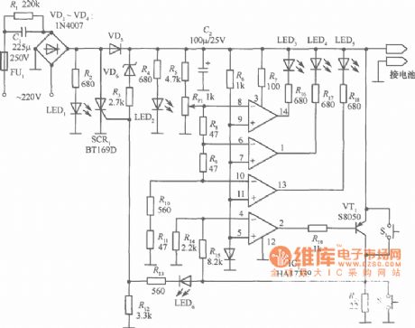
Lead-acid battery charger circuit diagram
Published:2014/3/4 19:55:00 Author:lynne | Keyword: Lead-acid battery charger circuit diagram,
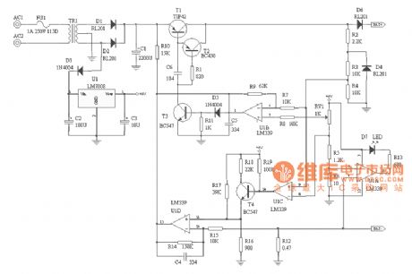
Because of the many advantages of sealed lead acid batteries , has received a wide range of applications . However, sealed lead-acid battery charging technology does not seem to be valued, because of the way unreasonable charging the battery prematurely scrapped caused widespread . In view of this , I designed a two-stage constant pressure limiting a lead-acid battery charger.Charging principles of analysis:1 maintenance charge :When the battery voltage is low ( can be set to a default in the circuit 9V or less ) , the charger work in small current maintenance charge state, the working principle is U1C ⑨ feet ( inverting terminal ) potential is lower than ⑧ feet ( inverting terminal ) , U1C output low , T4 deadline . U1D 11 feet potential of about 0.18V. At this point the charging current of about 250mA ( constant current circuit consists of R14, U1D, T1B surrounding peripheral circuits , constant self- analysis of the principle of the reader ) .2 Fast charging :With the continued maintenance charge , the battery voltage is gradually increased , when the battery voltage exceeds 9V, into high-current fast charge charger mode , U1C ⑨ feet ( inverting terminal ) potential higher than ⑧ feet ( inverting terminal ), U1C output high potential , T4 conduction , U1D 11 feet potential of about 0.48V, the charger output approximately constant 1A current to the battery .(3) limit pressure float :When the battery is nearly fully charged , the charger automatically transferred under pressure limiting floating state ( pressure limiting float voltage is set to 13.8V, such as 6V batteries, the float voltage should be set to 6.9V), this time charging current will gradually decrease from the fast charging, fully charged until the battery is fully charging current of only 10 ~ 30mA, to supplement the battery self-discharge and loss of power.4 circuit protection and charging indicator :The circuit has a reverse polarity protection circuit, the D4, U1C, U1D, T1 and peripheral components when reverse battery charger output current limiting without incident . Charging is indicated by U1A, D7 and peripheral components , charging , D7 lit, the battery charger into the floating state , D7 goes out , charging is finished.5 slightly modify the circuit parameters can be adjusted circuit charging current , float voltage battery with different specifications to meet the needs .Note : CF = carbon film resistors ; MF = Metal film resistors ; MOF = metal oxide film resistors* Can be adjusted according to said element .Lead-acid battery charger circuit diagram shown in Fig.:
(View)
View full Circuit Diagram | Comments | Reading(3653)
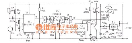
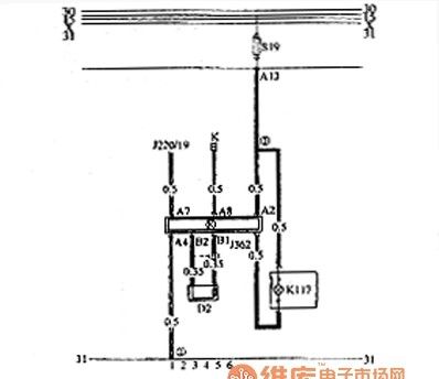
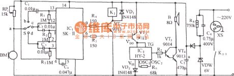
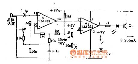
Infrared hood switch controller circuit
Published:2014/3/3 20:20:00 Author:lynne | Keyword: Infrared hood switch controller circuit,
Spend more and more kitchen range hood, it is the kitchen clean and a good helper. We have to press when using the power switch to turn on or off, when we hand full of greasy Would you expect this remarkable line trouble, always made the switch greasy. This circuit is the use of infrared light to control the switch as long as the palm of your hand too close to the switch stays on the line, like infrared faucets, very convenient and practical. Because it is close to using infrared, low power durable, energy-saving.
The circuit is mainly transmitted by infrared, receive, bistable switch and power circuit, as shown . R3, D3, C3 H to the receiving circuit to provide a stable 5V DC voltage. H quiescent current of 1 ~ 2mA. N4, N5 oscillation signal 32KHz , as amended by Q zoom out by the infrared emission tube D7. H receives the signal , high output, amplified by the C4 is coupled to N1 , N1 reverse output low, the flip -flop circuit , N3 high output, triac , exhaust fan work . If the received infrared signal H again , N2, N3 again flipped off SCR, hoods stopped . C5 N1 from interference and stable input level role , R4 is a pull-down resistor .Commissioning of high quality circuit board assembly , according to map production to succeed. Circuit board mounted on the wall switch in the original box . In the switch box cover drill two holes, hole distance of 2 cm, mounted at one end of the D7 sealed cylindrical hollow tube ( available toothpaste cap ), the translucent spout toward the hole, put another hole at the reception circuit H. After making a good integrated infrared transmitter and receiver tubes placed parallel to H ( H bald face and bald face parallel D7 ), internal definitely not light. Adjust the hand away from the D7 W about 15 to 20 cm can flip the circuit . (View)
View full Circuit Diagram | Comments | Reading(1943)
Dongfeng Peugeot Citroen Picasso 2.0L sedan starting and charging system circuit diagram
Published:2014/3/3 20:21:00 Author:lynne | Keyword: Dongfeng Peugeot Citroen Picasso 2.0L sedan starting and charging system circuit diagram,
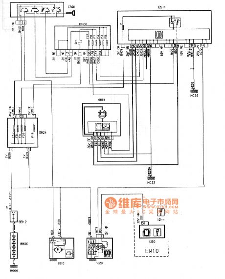
Dongfeng Peugeot Citroen Picasso 2.0L sedan starting and charging system circuit diagram shown in Fig.:
(View)
View full Circuit Diagram | Comments | Reading(1736)
Santana 2000GLs car air conditioning system circuit diagram
Published:2014/3/3 20:26:00 Author:lynne | Keyword: Santana 2000GLs car air conditioning system circuit diagram,
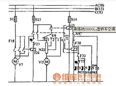
Santana 2000GLs car air conditioning system circuit diagram shown in Fig.:
(View)
View full Circuit Diagram | Comments | Reading(1412)
Ericsson phone charger circuit
Published:2014/3/3 20:34:00 Author:lynne | Keyword: Ericsson phone charger circuit,
Ericsson phone charger circuit shown in Figure:
(View)
View full Circuit Diagram | Comments | Reading(2856)
Voice-activated music outlet produced by SK-Ⅱ circuit diagram
Published:2014/3/3 20:36:00 Author:lynne | Keyword: Voice-activated music outlet produced by SK-Ⅱ circuit diagram,
Circuit is shown, which comprises an acoustic sensor, SK-Ⅱ voice circuit, the relay control circuit, a communication circuit, and the music sound buck rectifier circuit. BM acoustic / electric transducer. (View)
View full Circuit Diagram | Comments | Reading(1496)
Strobe lights drive circuit diagram
Published:2014/3/3 20:13:00 Author: | Keyword: Strobe lights drive circuit diagram,
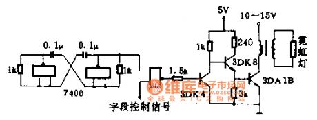
When the field control signal for low electricity at ordinary times, with the door closed, no signal output, this period is not bright neon lights.
1.5 K Ω for current-limiting resistance, protection, 3 dk4 value of B is good with 40-100, 3 dk4 B value in more than 40. Change 3 dk4 collector resistance, can change the current 3 dk4, to control the brightness of the light.
Magnetic core of pulse transformer with E12 at 11:45 type MXQ2000, primary 45 turns, wire diameter 0.51 mm enameled wire winding, the secondary use 0.21 mm high strength enamelled wire around 1500 turns. (View)
View full Circuit Diagram | Comments | Reading(1323)
Mazda headlight cleaners circuit diagram
Published:2014/3/3 20:11:00 Author: | Keyword: Mazda headlight cleaners circuit diagram,
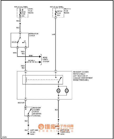
Mazda headlight cleaning device circuit diagram as shown (View)
View full Circuit Diagram | Comments | Reading(1797)
Sound incentive switch circuit diagram
Published:2014/3/3 20:10:00 Author: | Keyword: Sound incentive switch circuit diagram,
Sound incentive switch circuit diagram
(View)
View full Circuit Diagram | Comments | Reading(1404)
| Pages:17/2234 1234567891011121314151617181920Under 20 |
Circuit Categories
power supply circuit
Amplifier Circuit
Basic Circuit
LED and Light Circuit
Sensor Circuit
Signal Processing
Electrical Equipment Circuit
Control Circuit
Remote Control Circuit
A/D-D/A Converter Circuit
Audio Circuit
Measuring and Test Circuit
Communication Circuit
Computer-Related Circuit
555 Circuit
Automotive Circuit
Repairing Circuit