
Circuit Diagram
Index 18
Mazda headlight circuit diagram (DRL)
Published:2014/3/3 20:09:00 Author: | Keyword: Mazda headlight circuit diagram (DRL),
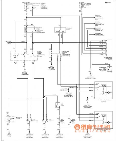
Mazda headlamps circuit diagram as shown (DRL) (View)
View full Circuit Diagram | Comments | Reading(2312)
Set method (multipath) driving display circuit diagram
Published:2014/3/3 20:05:00 Author: | Keyword: Set method (multipath) driving display circuit diagram,
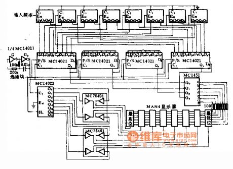
Set method (multipath) driving display circuit diagram
(View)
View full Circuit Diagram | Comments | Reading(1365)
Eight light-emitting diode drive circuit diagram
Published:2014/3/3 20:04:00 Author: | Keyword: Eight light-emitting diode drive circuit diagram,
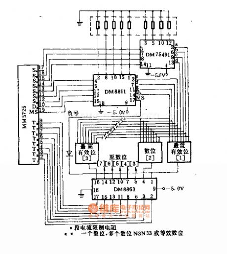
Eight light-emitting diode drive circuit diagram
(View)
View full Circuit Diagram | Comments | Reading(1316)
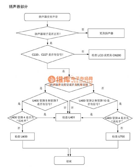
SGH - P408 troubleshooting and circuit principle diagram _11
Published:2014/3/3 20:03:00 Author: | Keyword: SGH - P408 troubleshooting and circuit principle diagram _11,
SGH as shown - P408 troubleshooting and circuit principle diagram _11 (View)
View full Circuit Diagram | Comments | Reading(1596)
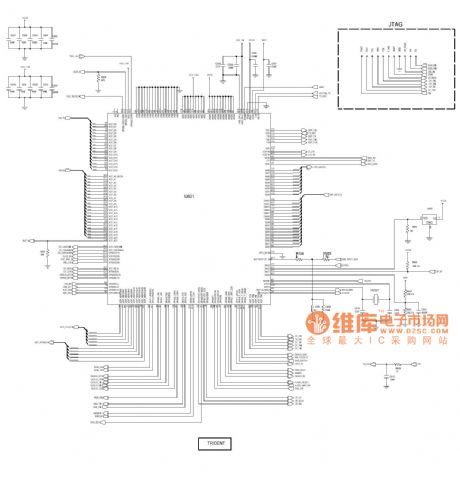
SGH - P408 troubleshooting and circuit principle diagram _12
Published:2014/3/3 19:59:00 Author: | Keyword: SGH - P408 troubleshooting and circuit principle diagram _12,
SGH as shown - P408 troubleshooting and circuit principle diagram _12 (View)
View full Circuit Diagram | Comments | Reading(1843)
Reverse polarity driving circuit diagram
Published:2014/3/3 19:58:00 Author: | Keyword: Reverse polarity driving circuit diagram,
Reverse polarity driving circuit diagram
(View)
View full Circuit Diagram | Comments | Reading(1351)
SGH - P408 troubleshooting and circuit principle diagram _13
Published:2014/3/3 19:57:00 Author: | Keyword: SGH - P408 troubleshooting and circuit principle diagram _13,
SGH as shown - P408 troubleshooting and circuit principle diagram _13 (View)
View full Circuit Diagram | Comments | Reading(1233)
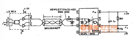
Visual CNC laser modulation drive circuit diagram
Published:2014/3/3 19:54:00 Author: | Keyword: Visual CNC laser modulation drive circuit diagram,
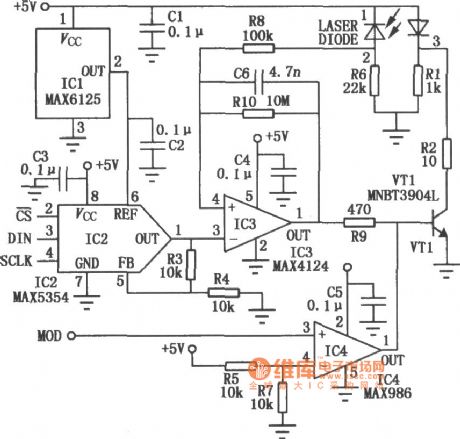
Visual CNC laser modulation drive circuit diagram
(View)
View full Circuit Diagram | Comments | Reading(1646)
Doppler automatic electronic switch circuit diagram
Published:2014/3/2 21:51:00 Author:lynne | Keyword: Doppler automatic electronic switch circuit diagram,
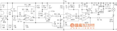
Resistor R7 is a weak positive feedback resistor every level, so that the high level once the pin ⑧, ⑧ pin so that the high voltage input of the voltage-inverting IC1d rises, causing the pin voltage rises IC1A ③, ① pin voltage rises , ⑦ pin voltage becomes lower, increasing the pulse width of the negative pin ⑦, so C6 sufficient charging time, the lamp is delayed to ensure consistency off.
(View)
View full Circuit Diagram | Comments | Reading(1906)
Dongfeng Peugeot Citroen Picasso 1.6L sedan starting and charging system circuit diagram
Published:2014/3/2 21:49:00 Author:lynne | Keyword: Dongfeng Peugeot Citroen Picasso 1.6L sedan starting and charging system circuit diagram,
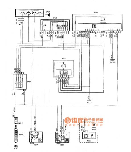
Dongfeng Peugeot Citroen Picasso 1.6L sedan starting and charging system circuit diagram shown in Fig.:
(View)
View full Circuit Diagram | Comments | Reading(1378)
hid electronic ballast circuit diagram
Published:2014/3/2 21:29:00 Author:lynne | Keyword: hid electronic ballast circuit diagram, IR2112

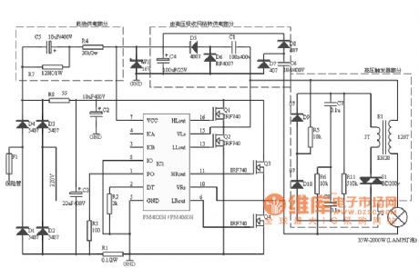
Using PM4020H design (HID) or high-pressure sodium lamp electronic ballast :Using high current push-pull circuit , can drive half-bridge and full- bridge circuit. Bridge output using low frequency AC , PM4020H single -ended drive built-in crossover frequency to 195Hz low frequency , thus eliminating the acoustic resonancePM4020H controllerHPM4020H control and drive HIDL integrates all the functions needed, it is suitable for metal halide ( such as car headlights, projector lamps, etc. ) , high-pressure mercury lamp and high pressure sodium high intensity discharge lamp controller driver and control. It contains a complete current mode pulse width modulator, a lamp power regulator, lamp temperature compensator and all fault protection.HPM4020H structure and function shown in Figure 1 . Using high current push-pull circuit , can drive half-bridge and full- bridge circuit. Bridge output using low frequency AC , PM4020H single -ended drive built-in crossover frequency to 195Hz low frequency , thus eliminating acoustic resonance . The discharge arc is unstable acoustic resonance phenomenon occurs when a high-frequency HIDL supply mechanism is pulsating pressure wave in the lamp is reflected from the inner wall of the tube , if the phase of the pulsed high-frequency current component is the same , the formation of standing waves generating acoustic resonance , ranging from light shake , heavy burning lamps and ballasts.As shown in Figure 1 shows the structure and function of HPM4020H:
Output of the controller uses a full-bridge inverter. The inverter operates at the frequency 195Hz, the average lamp voltage is zero. Bridge is driven by foot QOUT and QOUT output, they are 50% duty cycle, a difference of 180 °. Using IR2112 driver high and low of the MOSFET. The cost of this approach is expensive, can directly drive the low-end and high-end using a high-voltage transistor, a resistor and pull the correct phase. The following is a detailed circuit diagram.
(View)
View full Circuit Diagram | Comments | Reading(5096)
Dongfeng Peugeot Citroen Picasso 2.0L car theft transponder circuit
Published:2014/3/2 21:18:00 Author:lynne | Keyword: Dongfeng Peugeot Citroen Picasso 2.0L car theft transponder circuit,
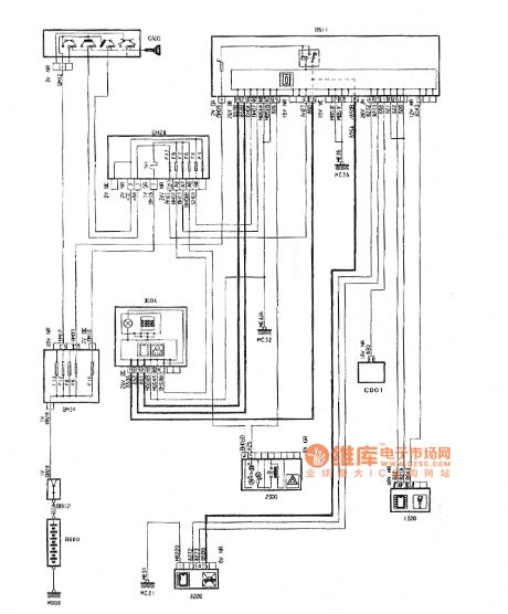
Dongfeng Peugeot Citroen Picasso 2.0L car theft transponder circuit shown in Figure:
(View)
View full Circuit Diagram | Comments | Reading(1254)
50w electronic ballast circuit diagram
Published:2014/3/2 20:39:00 Author:lynne | Keyword: 50w electronic ballast circuit diagram, IN4007, C3093, AC220V
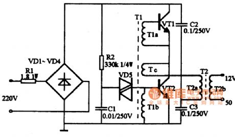
This circuit shows the electronic transformer, input AC220V, output is AC12V, power up to 50W. It is primarily developed out on the basis of high-frequency electronic ballast circuit on a transformer circuit, stable performance, small size, high power, thus overcoming the traditional silicon steel transformer body big, bulky, price higher shortcomings.
Circuit is shown below. It works similar to the switching power supply, a diode bridge rectifier VD1 ~ VD4 constitute the mains into DC, high frequency oscillation circuit from oscillating transformer T1, the transistor VT1, VT2 composed of the pulsating DC into high frequency current, and then the iron Oxygen output transformer T2 high-frequency high-voltage pulse pressure, to obtain the desired voltage and power. R1 is a current limiting resistor. Resistor R2, capacitors C1 and bidirectional trigger diode VD5 constitute started trigger circuit. Transistor VT1, VT2 selection S13005, the B 15 to 20 times. C3093 can also be used, such as BUceo> = 35OV the power transistor. Trigger diode DB3 about VD5 use 32V or VR60. Oscillation transformer can be made with the audio-wound toroid on H7 X 10 X 6's. TIa, T1b 3 turns around, Tc around a turn. Ferrite output transformer T2 also need self-control, core selection of side length 27mm, width 20mm, 10mm thick EI type ferrite. T2a with a diameter of 0.45mm high strength wire wound 100 turns, T2b around with a diameter of 1.25mm high strength wire 8 turns. Selection IN4007 diode VD1 ~ VD4 type, two-way trigger diode DB3 type selection, selection of polypropylene capacitors C1 ~ C3 Polyester capacitors, voltage 250V.
When the circuit work, A point of working voltage of about 12V; B point about 25V; C point about 105V; D point about 10V. If the voltage does not meet the above values, or the circuit does not oscillate, you should check whether the fault circuit welding, weld or Weld. Then check VT1, VT2 is good, T1a, T1b phase is correct. After the success of the entire circuit alignment, can be loaded with a small box made of metal material, made conducive shielding and heat dissipation, but must pay attention to insulation circuit and housing. Cited, the change in T2 a, b two coil turns, you can change the high-frequency voltage output.
50w electronic ballast circuit diagram shown in Fig. :
(View)
View full Circuit Diagram | Comments | Reading(2435)
400 hz light-emitting diode p combination of sine wave with operational amplifier circuit diagram
Published:2014/3/2 21:44:00 Author: | Keyword: 400 hz light-emitting diode p combination of sine wave with operational amplifier circuit diagram,
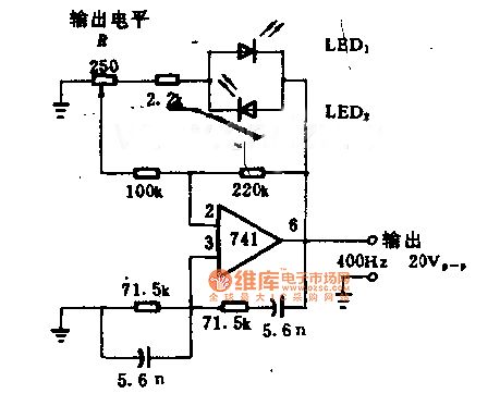
400 hz light-emitting diode p combination of sine wave with operational amplifier circuit diagram
(View)
View full Circuit Diagram | Comments | Reading(1461)
Photosensitive type oscillation circuit diagram
Published:2014/3/2 21:35:00 Author: | Keyword: Photosensitive type oscillation circuit diagram,
Photosensitive type oscillation circuit diagram
(View)
View full Circuit Diagram | Comments | Reading(1308)
SGH - P408 troubleshooting and circuit principle diagram _14
Published:2014/3/2 21:33:00 Author: | Keyword: SGH - P408 troubleshooting and circuit principle diagram _14,
SGH as shown - P408 troubleshooting and circuit principle diagram _14 (View)
View full Circuit Diagram | Comments | Reading(1174)
Excelle electronic evaporative emission carbon can purge solenoid valve, camshaft position sensor, instrument cluster, and the speed sensor circuit diagram
Published:2014/3/2 21:32:00 Author: | Keyword: Excelle electronic evaporative emission carbon can purge solenoid valve, camshaft position sensor, instrument cluster, and the speed sensor circuit diagram,
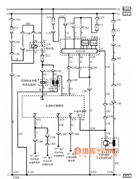
Excelle electronic evaporative emission carbon tank as shown purge solenoid valve, camshaft position sensor, instrument cluster, and the speed sensor circuit diagram (View)
View full Circuit Diagram | Comments | Reading(1409)
With double trigger a demo circuit diagram
Published:2014/3/2 21:31:00 Author: | Keyword: With double trigger a demo circuit diagram,
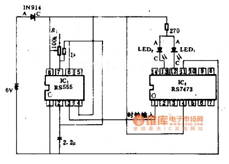
With double trigger a demo circuit diagram
(View)
View full Circuit Diagram | Comments | Reading(1349)
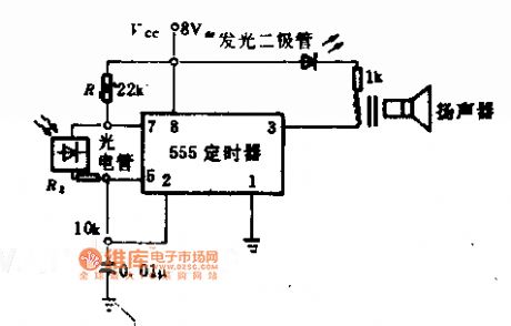
5 KHS photocell oscillation circuit diagram
Published:2014/3/2 21:29:00 Author: | Keyword: 5 KHS photocell oscillation circuit diagram,
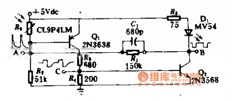
5 KHS photocell oscillation circuit diagram
(View)
View full Circuit Diagram | Comments | Reading(1342)
Solar power oscillation circuit diagram
Published:2014/3/2 21:28:00 Author: | Keyword: Solar power oscillation circuit diagram,
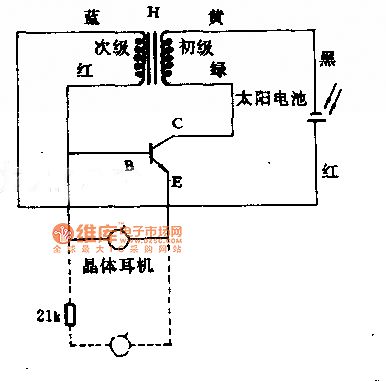

Solar power oscillation circuit diagram
(View)
View full Circuit Diagram | Comments | Reading(1521)
| Pages:18/2234 1234567891011121314151617181920Under 20 |
Circuit Categories
power supply circuit
Amplifier Circuit
Basic Circuit
LED and Light Circuit
Sensor Circuit
Signal Processing
Electrical Equipment Circuit
Control Circuit
Remote Control Circuit
A/D-D/A Converter Circuit
Audio Circuit
Measuring and Test Circuit
Communication Circuit
Computer-Related Circuit
555 Circuit
Automotive Circuit
Repairing Circuit