
Circuit Diagram
Index 13
AIC1896 integrated circuit diagram
Published:2014/3/16 21:13:00 Author:lynne | Keyword: AIC1896 integrated circuit diagram, AIC1896
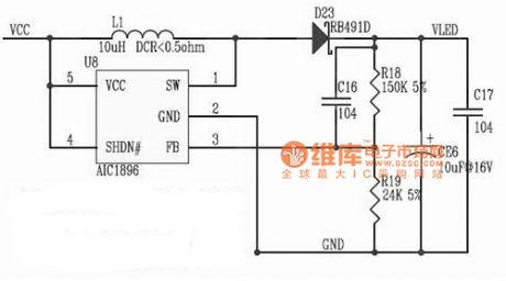
AIC1896 integrated circuit diagram shown as follow:
(View)
View full Circuit Diagram | Comments | Reading(1547)
ZTE mobile phone charger circuit diagram
Published:2014/3/16 21:12:00 Author:lynne | Keyword: ZTE mobile phone charger circuit diagram,

ZTE mobile phone charger circuit diagram as shown:
(View)
View full Circuit Diagram | Comments | Reading(3724)
DC low-voltage regulated power supply circuit
Published:2014/3/16 21:11:00 Author:lynne | Keyword: DC low-voltage regulated power supply circuit, NE555
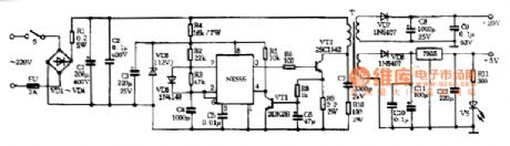
Switching power supply portion VD1-VD4, R1, C1, C2 smoothing circuit composed of the rectifier . NE555 and R2, R3, C4, VD6 other components multivibrator circuit , its frequency is about 20KHz. R4, C3, VD5 composition buck regulator circuit , as NE555 provides 12V power supply. High-power tube VT1 and transformer T constitutes a switching circuit . NE555 VT1 working state by the foot control of ③ , the conduction time is determined by the pulse width , the pulse width can be changed to adjust R3 . Wider pulse width , the output voltage increases ; narrowing the pulse width , the output voltage is reduced. VT2 and R8, R9, C6 composition overcurrent protection circuit . When overloaded or short-circuit fault , VT2 conduction, forced NE555 reset stop vibration , thereby protecting VT1 without damage. C7, R10 to protect the network and prevent the breakdown of VT1 ce knot instantaneous pulse . After two secondary windings are rectified and filtered output of 20V and 12V.In order to make simple , switching power supply designed to not automatically regulated , its function is similar to a transformer , only to realize the light of the antihypertensive effect of isolation , voltage regulation implemented by the back of the regulator circuit . 12V DC voltage by 7805 the +5 V output voltage ; 20V adjustable DC voltage to the voltage regulator circuit . No common ground between the two , in order to add or subtract a combination of a variety of output voltages.DC low voltage power supply circuit shown in Figure:
(View)
View full Circuit Diagram | Comments | Reading(3519)
Tube full-wave rectified and filtered circuit Diagram
Published:2014/3/16 21:09:00 Author:lynne | Keyword: Tube full-wave rectified and filtered circuit Diagram,

Tube full-wave rectified and filtered circuit Diagram shown as follow:
(View)
View full Circuit Diagram | Comments | Reading(1309)
Using TC620 temperature sensor circuit diagram of computer room thermostat
Published:2014/3/16 21:07:00 Author:lynne | Keyword: Using TC620 temperature sensor circuit diagram of computer room thermostat, TC620
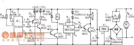
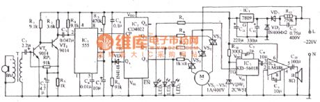
The circuit shown in FIG it by a temperature sensor, a control device, the minimum temperature of the display, the motor relay control circuit, the analog sound waves buck rectifier circuit and the AC circuit. (View)
View full Circuit Diagram | Comments | Reading(2776)
PC, CPU overheat language warned circuit diagram
Published:2014/3/13 23:04:00 Author:lynne | Keyword: PC, CPU overheat language warned circuit diagram,

The circuit shown in FIG. It consists of a temperature sensor, temperature electronic switch circuit composed of sound and language. On hot summer season, PC's central processing unit CPU overheating often, the circuit VT1 die close to the CPU chip, radiator, once the CPU overheating, the circuit will issue a Notice that temperature cautioned statement, reminded officers to take measures to cool. (View)
View full Circuit Diagram | Comments | Reading(1495)
The doppler effect and double control automatic door light socket (RD627) circuit
Published:2014/3/13 23:03:00 Author:lynne | Keyword: The doppler effect and double control automatic door light socket (RD627) circuit, RD627
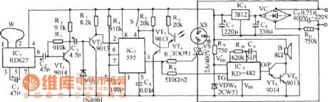
The circuit shown in FIG. It consists of the Doppler effect sensor head, light control switch, one-shot, SCR control circuit, vocal music buck rectifier circuit and the AC circuit. When a vehicle or pedestrian approached the front door, security door will open automatically, but will be broadcast on a melodious song. (View)
View full Circuit Diagram | Comments | Reading(2681)
With TWH9205 photoelectric coupling type zero control socket circuit diagram
Published:2014/3/13 23:01:00 Author:lynne | Keyword: With TWH9205 photoelectric coupling type zero control socket circuit diagram,
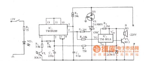
Circuit is shown, which includes zero-drive switch, the optical coupler type input circuit, a control circuit and the thyristor circuit audible sound. FIG phototransistor switch circuit connected to the inverting input terminal of the differential switch TWH9205 amplifier (9 feet), when the terminal voltage is lower than the inverting input terminal of the clamping voltage, that is, when irradiated with light photocell 3DU5, TWH9205 AC output high zero crossing before driving thyristor VS and conduction, XS was electric socket, electrical equipment and XS link into operation. VS according to the size of the electrical load power, the choice of triac 1 ~ 500A. (View)
View full Circuit Diagram | Comments | Reading(1503)
Motor overheating language newspaper called circuit diagram
Published:2014/3/13 22:59:00 Author:lynne | Keyword: Motor overheating language newspaper called circuit diagram,
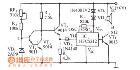
The circuit shown in FIG. It consists of a temperature sensor, electronic circuit and the switching circuit composed of the language utterance. In the hot season, or when the temperature of the motor fails to run, often the motor overheating. The circuit can issue a beep, please note that the language of caution in the motor housing temperature alert duty personnel in order to avoid burn out the motor.
(View)
View full Circuit Diagram | Comments | Reading(1319)
Undervoltage alarm circuit diagram
Published:2014/3/13 22:58:00 Author:lynne | Keyword: Undervoltage alarm circuit diagram,
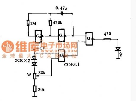
This circuit is a low-pressure alarm circuit 5V power supply, only one and not gate CC4011, with LED indication. Circuit is simple, reliable, low-power consumption. Supply voltage is high enough, G1 output low, G2 output high, light-emitting diodes. When the supply voltage drops to the set value, an input terminal of the G3 becomes a low voltage, high output G1. Thus, the pulse oscillator G3, G4 composition produced by the light emitting diode G2 flash frequency of the oscillator frequency, three times per second.When mediation, just need power plus the minimum allowable value (eg 4V), then change the position of the potentiometer arm, so that the output of G1 can just flip.
(View)
View full Circuit Diagram | Comments | Reading(1848)
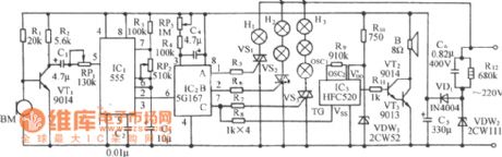
Sound speed and cricket fans disgrace vocal control circuit diagrams
Published:2014/3/13 2:50:00 Author:lynne | Keyword: Sound speed and cricket fans disgrace vocal control circuit diagrams,
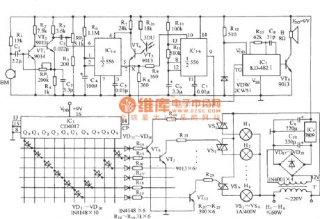
Circuit as shown, it includes acoustic sensor, audio amplifier, monostable trigger circuit, pulse counting/distribution circuit, thyristor speed regulation circuit, crickets sound circuit and ac step-down rectifier circuit, etc. Circuit using burst (such as punch, password) acoustic mode, three block wind speed can be control and stalling control, in the fan blowing at the same time, accompanied by filar silk cool meaning of crickets cry, strong anti-interference characteristics. (View)
View full Circuit Diagram | Comments | Reading(1690)
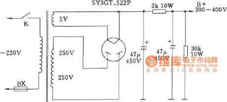
Tube high voltage circuit diagram
Published:2014/3/13 2:40:00 Author:lynne | Keyword: Tube high voltage circuit diagram,
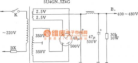
Tube high voltage circuit diagram shown as follow:
(View)
View full Circuit Diagram | Comments | Reading(1355)
Acousto-optic double two-way flow control lights with music voice circuit diagram
Published:2014/3/13 2:43:00 Author:lynne | Keyword: Acousto-optic double two-way flow control lights with music voice circuit diagram,
Circuit is shown, which consists of voice electronic switch, light control switch, one-shot, controllable multivibrator circuit vocal music, counting / pulse distribution circuit ring, six-way driver circuit and the AC buck Lantern rectifier circuit. It can be a two-way flow in the lights, it is also accompanied by melodious music more than the first, Streamer, melodious music. (View)
View full Circuit Diagram | Comments | Reading(4962)
Battery level indicator circuit diagram
Published:2014/3/13 2:46:00 Author:lynne | Keyword: Battery level indicator circuit diagram,
Battery level indicator circuit diagram shown as follow:
(View)
View full Circuit Diagram | Comments | Reading(1590)
5G0401 acoustic synchronous flash with disco drum music circuit diagram
Published:2014/3/13 2:47:00 Author:lynne | Keyword: 5G0401 acoustic synchronous flash with disco drum music circuit diagram, 5G0401
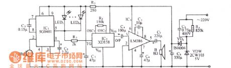
Circuit shown in Figure, which includes voice-activated flash circuit, drum music sound circuit and audio amplifier circuit and buck rectifier circuit. 5G0401 is the voice flash drive ASIC. (View)
View full Circuit Diagram | Comments | Reading(1423)
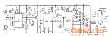
Acousto-optic double eight-way lantern with 12 songs sound circuit control(BH - SH - II) circuit diagram
Published:2014/3/11 23:02:00 Author:lynne | Keyword: Acousto-optic double eight-way lantern with 12 songs sound circuit control(BH - SH - II) circuit diagram, BH - SH - II

The circuit shown in FIG. It consists of voice electronic switch, light control switch, vocal music circuit, audio amplifier circuit, multivibrator timing distribution circuit, audio control switch circuit, thyristor drive circuit and the AC buck rectifier circuit. The circuit in the broadcast world music, while eight sparkling lights synchronized with music, Streamer, fickle. (View)
View full Circuit Diagram | Comments | Reading(2695)
Voice control type two-way water lights with the sound control circuit (5G167) circuit diagram
Published:2014/3/11 23:00:00 Author:lynne | Keyword: Voice control type two-way water lights with the sound control circuit (5G167) circuit diagram, 5G167
Circuit is shown, which consists of voice circuits, one-shot, the ring count pulse distribution / driver circuit, thyristor trigger control circuit, audible sound of the waves and the AC buck rectifier circuit and other components, which enables three-way bidirectional string lights automatically flip water and rocks with waves hitting the coast or natural sound. (View)
View full Circuit Diagram | Comments | Reading(2839)
7812 regulated power supply circuit
Published:2014/3/11 22:58:00 Author:lynne | Keyword: 7812 regulated power supply circuit, 7812
7812 regulated power supply circuit shown as follow:
(View)
View full Circuit Diagram | Comments | Reading(2227)
With SH805 acousto-optic double control lights with music voice circuit diagram
Published:2014/3/11 22:56:00 Author:lynne | Keyword: With SH805 acousto-optic double control lights with music voice circuit diagram, SH805
The circuit shown in the figure, which consists of voice-activated switch, light control switch, one-shot timer circuit, control circuit and lights music sound circuit. The light control circuit 16 functions program can automatically transform, colorful, and its control method is sound, light double control, not light during the day, at night before proceeding voice. In the flickering lights, it is also accompanied by sweet waltz music. (View)
View full Circuit Diagram | Comments | Reading(2453)
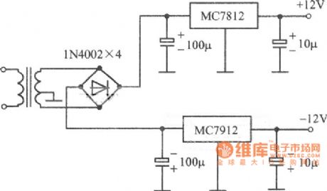
7815 regulated power supply circuit
Published:2014/3/11 22:49:00 Author:lynne | Keyword: 7815 regulated power supply circuit, 7815
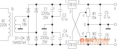
Continuously adjustable dual power ( positive and negative symmetrical power supply ) . This circuit consists of a symmetrical connection 7815 and a 7915 three-terminal regulator , you can get a set of positive and negative symmetrical power supply, and the output voltage can be adjusted individually each , can also be synchronized adjustment.Circuit as shown , the AC output from the transformer voltage by 18V double rectifier D1 ~ D4 , C1, C2 obtained by filtering a DC voltage, wherein the dual power transformer center tap as a common ground, and each of the positive and negative of the DC voltage access ① 7815 and 7915 feet of ③ feet. ③ 7815 feet of sliding contacts connected to the potentiometer W2 of d , the pin 7915 to the potentiometer ① sliding contact piece W1 C on . When the contacts C slide 0 when terminated , the regulator W2, to a and end get +6 ~ +15 V Forward variable voltage ; contacts If d slide 0 termination , the regulator W1, in the b side can get -6 ~-15V negative variable voltage, W1, W2 into coaxial potentiometer obtain the symmetrical adjustable power supply , the output voltage is continuously adjustable between ± 6V ~ ± 15V, can be synchronized adjustment purposes.7815,7915 heatsink should be installed on the three-terminal voltage regulator circuit block , do heat dissipation .7815 regulated power supply circuit shown in Fig.
(View)
View full Circuit Diagram | Comments | Reading(3427)
| Pages:13/2234 1234567891011121314151617181920Under 20 |
Circuit Categories
power supply circuit
Amplifier Circuit
Basic Circuit
LED and Light Circuit
Sensor Circuit
Signal Processing
Electrical Equipment Circuit
Control Circuit
Remote Control Circuit
A/D-D/A Converter Circuit
Audio Circuit
Measuring and Test Circuit
Communication Circuit
Computer-Related Circuit
555 Circuit
Automotive Circuit
Repairing Circuit