
Circuit Diagram
Index 15
TEA1523P power circuit
Published:2014/3/9 21:39:00 Author:lynne | Keyword: TEA1523P power circuit, TEA1523P
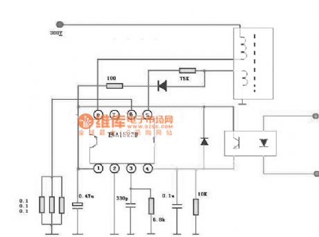
TEA1523P power circuit shown as follow:
(View)
View full Circuit Diagram | Comments | Reading(5887)
5GMl68 audio voltage-controlled festival lantern control circuit diagram
Published:2014/3/9 21:41:00 Author:lynne | Keyword: 5GMl68 audio voltage-controlled festival lantern control circuit diagram, 5GMl68
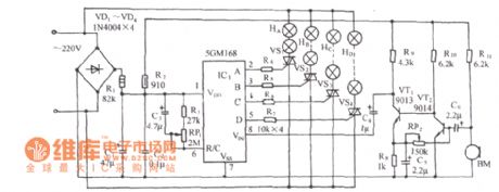
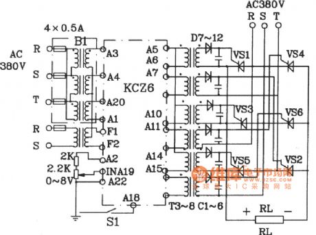
As shown for the introduction of four lights 5GM168 composed of a control circuit (chip G-foot vacant), after four output current limiting resistor added to each VS1 ~ VS4 gate control their lights off and the corresponding road lanterns. BM is a pickup sensor. (View)
View full Circuit Diagram | Comments | Reading(2269)
Sound control birdsong lights circuit(555、KD-5602) schematic
Published:2014/3/6 20:49:00 Author:lynne | Keyword: Sound control birdsong lights circuit(555、KD-5602) schematic,
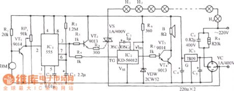
The circuit shown in FIG. It consists of acoustic / electric sensors trigger timing circuit, thyristor trigger control circuit, birds sound buck rectifier circuit and the AC circuit. (View)
View full Circuit Diagram | Comments | Reading(2502)
Hardware circuit ultrasonic range finder
Published:2014/3/6 20:53:00 Author:lynne | Keyword: Hardware circuit ultrasonic range finder,
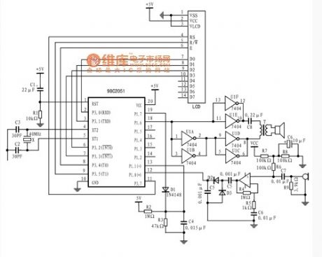


AT89C2051 by external pin P1.6 output pulse width is 250μs, the carrier is 10 pulses of 40kHz pulse group, added to the push-pull transformer primary form by upconverting promote emitted ultrasonic transducer. Simultaneously transmitted, P1.7 outputs a high level starts to charge the capacitor C4. The transmitting end toggles LOW HIGH divider C4 starts R2, R3, and the composition discharged to the negative output terminal of the comparator. Ultrasonic receiving transducer converts the received ultrasonic waves reflected by an obstacle to the amplifier for amplification, which is a high gain, low noise amplifier, the positive input of the detection signal will be amplified to detect the echo of the comparator end. The emission level of the output P1.7 can suppress the comparator flip, it can be suppressed so that the transmitter transmits the ultrasonic wave radiated to the error detection result of the receiver.
(View)
View full Circuit Diagram | Comments | Reading(2219)
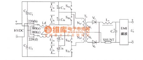
Three-phase full-bridge application circuit diagram
Published:2014/3/6 20:55:00 Author:lynne | Keyword: Three-phase full-bridge application circuit diagram,
Pulse transformer can be tank-shaped Mn-Zn ferrite. Generally used U30 core or SEAR2: l pulse transformer. Three-phase full-bridge circuit diagram shown in Figure Application...
(View)
View full Circuit Diagram | Comments | Reading(1622)
uc3842 switching power supply circuit
Published:2014/3/6 20:56:00 Author:lynne | Keyword: uc3842 switching power supply circuit, uc3842

uc3842 switching power supply circuit shown in figure:
(View)
View full Circuit Diagram | Comments | Reading(14362)
Research sensor schematic circuit
Published:2014/3/6 20:57:00 Author:lynne | Keyword: Research sensor schematic circuit
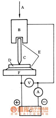
Figure: is a schematic diagram of Sensors A-adjustable pressure, B-metal needle electrode clamps, C-metal needle electrode, D-perovskite type oxide thin, E-or carbon-based conductive silver paste, F-metal a substrate, G-DC power supply.
(View)
View full Circuit Diagram | Comments | Reading(2176)
DMAl2 main circuit principle diagram
Published:2014/3/6 20:13:00 Author: | Keyword: DMAl2 main circuit principle diagram,
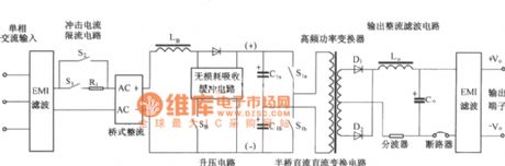
As shown for simplified DMA12 main circuit principle diagram. It is mainly composed of input circuit and electromagnetic interference (EMI) filter circuit, impact current limiting circuit, input rectifier filter circuit, booster/power factor correction circuit and absorption circuit, a half-bridge power conversion circuit, the output rectifier filter circuit, etc. Compared with DMA10, DMA12 adopted single phase input, booster/power factor correction method and the lossless absorption buffer circuit, and half bridge DC/DC power conversion and output rectifier filter part like the DMA10. (View)
View full Circuit Diagram | Comments | Reading(1398)
DMAl2 constitute a circuit diagram
Published:2014/3/6 20:13:00 Author: | Keyword: DMAl2 constitute a circuit diagram,
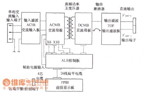
DMA12 intelligent switch rectifier module by the ac input board (ACIB), the exchange motherboard (ACMB), dc motherboard (DCMB), output filter plate (TOF), control panel (propagated), shown earlier (FPBI) six boards printed circuit board and input/output plugs, circuit breakers, inductance and transformer etc, as shown. (View)
View full Circuit Diagram | Comments | Reading(1425)
P4 power supply circuit diagram
Published:2014/3/6 20:12:00 Author: | Keyword: P4 power supply circuit diagram,
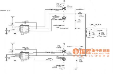
P4 power supply circuit diagram as shown (View)
View full Circuit Diagram | Comments | Reading(1829)
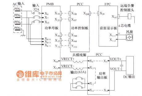
DUM23-48/300 Ⅱ dc power distribution unit electrical principle diagram
Published:2014/3/6 20:10:00 Author: | Keyword: DUM23-48/300 Ⅱ dc power distribution unit electrical principle diagram,
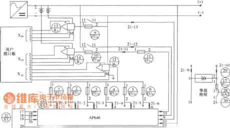
As shown in figure, B2 (13), B3 (14) for the hall current sensor; FU9 (9), FU10 (10) for the fuse; AP646 for fusing the alarm signal board; X24, X26 and X29 for user interface board of the terminal; XT for socket. (View)
View full Circuit Diagram | Comments | Reading(1776)
Samsung E700 type mobile phone line circuit principle diagram
Published:2014/3/6 20:07:00 Author: | Keyword: Samsung E700 type mobile phone line circuit principle diagram,
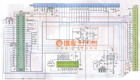
As shown in the samsung E700 type mobile phone line circuit principle diagram (View)
View full Circuit Diagram | Comments | Reading(1627)
Mazda ABS circuit diagram
Published:2014/3/6 20:06:00 Author: | Keyword: Mazda ABS circuit diagram,
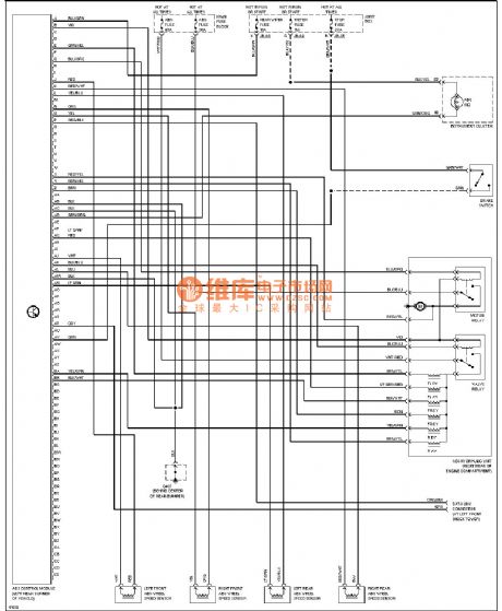
Mazda ABS circuit diagram as shown (View)
View full Circuit Diagram | Comments | Reading(1416)
Ii DUM23-48/300 principle of ac power distribution unit electric circuit diagram
Published:2014/3/6 20:05:00 Author: | Keyword: Ii DUM23-48/300 principle of ac power distribution unit electric circuit diagram,

View full Circuit Diagram | Comments | Reading(1700)
Mazda reversing light circuit diagram
Published:2014/3/6 20:04:00 Author: | Keyword: Mazda reversing light circuit diagram,
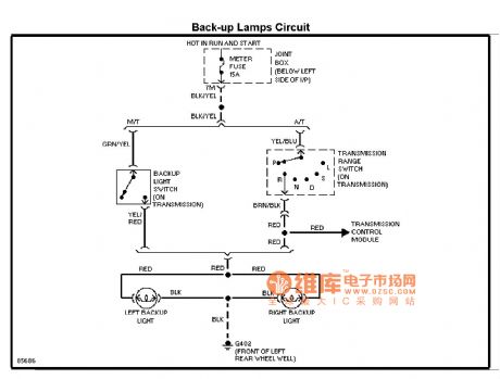
Mazda pour lamp circuit diagram as shown (View)
View full Circuit Diagram | Comments | Reading(1910)
Mazda charging circuit diagram
Published:2014/3/6 20:00:00 Author: | Keyword: Mazda charging circuit diagram,
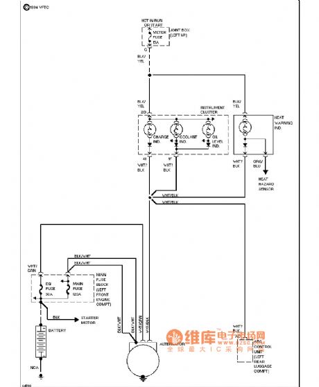
Mazda charging system diagram as shown (View)
View full Circuit Diagram | Comments | Reading(2015)
DMAl0 double half bridge commutation circuit principle diagram
Published:2014/3/6 19:58:00 Author: | Keyword: DMAl0 double half bridge commutation circuit principle diagram,


DMAl0 main circuit work waveform:
(View)
View full Circuit Diagram | Comments | Reading(1524)
The DMA input circuit diagram
Published:2014/3/6 19:56:00 Author: | Keyword: The DMA input circuit diagram,

View full Circuit Diagram | Comments | Reading(1425)
DMAl0 rectifier module structure diagram
Published:2014/3/6 19:54:00 Author: | Keyword: DMAl0 rectifier module structure diagram,
View full Circuit Diagram | Comments | Reading(1212)
Motherboard power supply circuit diagram
Published:2014/3/5 21:42:00 Author:lynne | Keyword: Motherboard power supply circuit diagram,
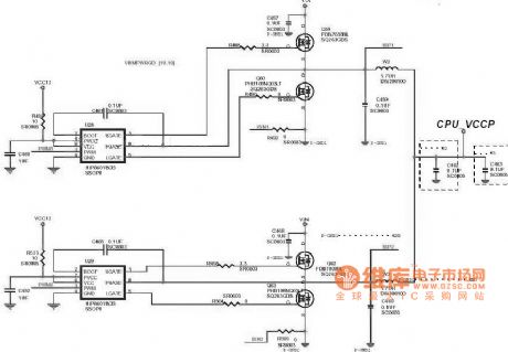
Motherboard power supply circuit diagram as shown:
(View)
View full Circuit Diagram | Comments | Reading(2591)
| Pages:15/2234 1234567891011121314151617181920Under 20 |
Circuit Categories
power supply circuit
Amplifier Circuit
Basic Circuit
LED and Light Circuit
Sensor Circuit
Signal Processing
Electrical Equipment Circuit
Control Circuit
Remote Control Circuit
A/D-D/A Converter Circuit
Audio Circuit
Measuring and Test Circuit
Communication Circuit
Computer-Related Circuit
555 Circuit
Automotive Circuit
Repairing Circuit