
Circuit Diagram
Index 800
SIMPLE_RIPPLE_SUPPRESSOR
Published:2009/7/10 22:15:00 Author:May
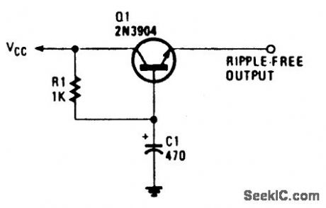
This circuit, at times called a capacitance multiplier, is useful for suppressing power-supply ripple. C1 provides filtering equal to a capacitor of (B+1) C1, where B=dc current gain of Q1 (typically > 50). (View)
View full Circuit Diagram | Comments | Reading(0)
30_MHz_video_amplifier_using_an_MC1552G
Published:2009/7/17 4:44:00 Author:Jessie
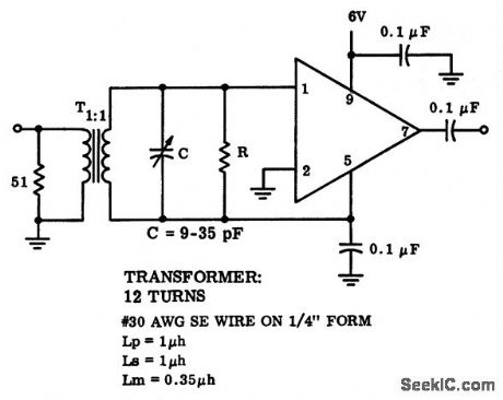
30 MHz video amplifier using an MC1552G.Set R to 1 K for a voltage gain of 55(courtesy Motorola semiconductor Products Inc.). (View)
View full Circuit Diagram | Comments | Reading(693)
TELEPHONE_SPEAKER_AMPLIFIER
Published:2009/7/10 22:14:00 Author:May
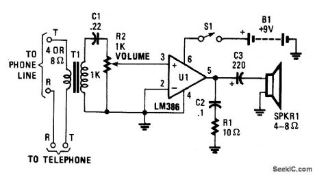
This simple telephone amplifier (which can be switched off for privacy) allows everyone in the room to listen to your telephone conversations. (View)
View full Circuit Diagram | Comments | Reading(2257)
Norton_noninverting_low_voltage_comparator
Published:2009/7/17 4:44:00 Author:Jessie
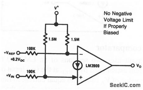
This circuit uses one section of an LM3900 to form a noninverting comparator. The circuit can compare voltages between zero and 1V, as well as large negative voltages. When working with negative voltages, the current supplied by the common-mode network must be large enough to satisfy both the current-drain demands of the input voltages, and the bias-current requirements of the amplifier. National Semiconductor, Linear Applications Handbook 1991 p. 243 (View)
View full Circuit Diagram | Comments | Reading(888)
REGULATED_CHARGE_PUMP
Published:2009/7/10 22:13:00 Author:May
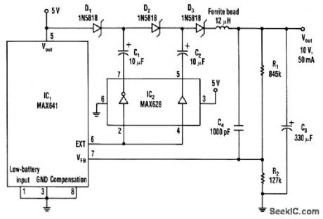
The dc-dc converter substitutes a voltage tripler in place of the external inductor and the diode that's typically associated with the switching regulator, IC1. Inverting and noninverting amplifiers in the MOS-FET-driver (IC2) activate a diode-capacitor tripling network (D1 through D3, C1 through C3).A 50-kHz oscillator residing within IC1 produces the EXT signal (pin 6). IC2 converts this signal into drive signals (180°out of phase) for the tripler. The resulting charge-discharge action in the capacitors recharges C3 toward 10 V every 20 μs. The ferrite bead limits output ripple to about 20-m Vpp for a 50-mA load. Conversion efficiency is about 70% for the 5-V input, 10-V output configuration. (View)
View full Circuit Diagram | Comments | Reading(827)
1_KC_NOISE_FIGURE_TEST_SET
Published:2009/7/17 4:44:00 Author:Jessie
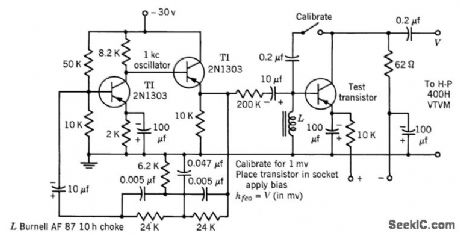
Used in measuring low-frequency Gommon-emitter short-circuit forward current transfer ratio h-feo, which is one of the parameters having greatest effect on transistor noise figure. -Texas Instruments Inc., Transistor Circuit Design, McGraw-Hill, N.Y., 1963, p 304. (View)
View full Circuit Diagram | Comments | Reading(748)
LOW_POWER_TOUCH_TONE_DECODER
Published:2009/7/10 22:11:00 Author:May
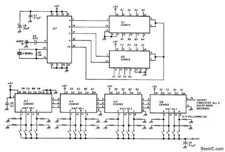
This decoder will respond to a preselected 4-digit DTMF number. IC7 is a Radio Shack IC device (part #276-1303). The logic is all CMOS. The digits are selected by SW1 and SW2, a pair of 8-position DIP switches. (View)
View full Circuit Diagram | Comments | Reading(2035)
Wide_band_video_amplifier_using_an_ECG915_operational_amplifier_with_75_ohm_coax_drive_capability
Published:2009/7/17 4:44:00 Author:Jessie
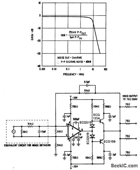
Wide-band video amplifier using an ECG915 operational amplifier with 75-ohm coax drive capability (courtesy GTE Sylvania Incorporated). (View)
View full Circuit Diagram | Comments | Reading(788)
Norton_comparator_for_positive_input_voltages
Published:2009/7/17 4:43:00 Author:Jessie
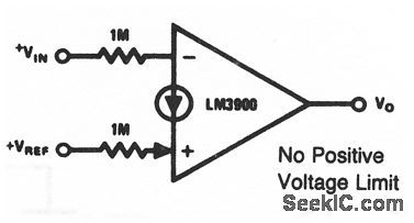
This circuit uses one section of an LM3900 to form an inverting comparator. The reference voltage must be larger than VBE (typically 0.5 V), but there is no limit as long as the input resistor is large enough to guarantee that the input current does not exceed 200μA. National Semiconductor Linear Applications Handbook 1991, p 243. (View)
View full Circuit Diagram | Comments | Reading(651)
SCANNING_ASCI_NECODER
Published:2009/7/10 22:10:00 Author:May
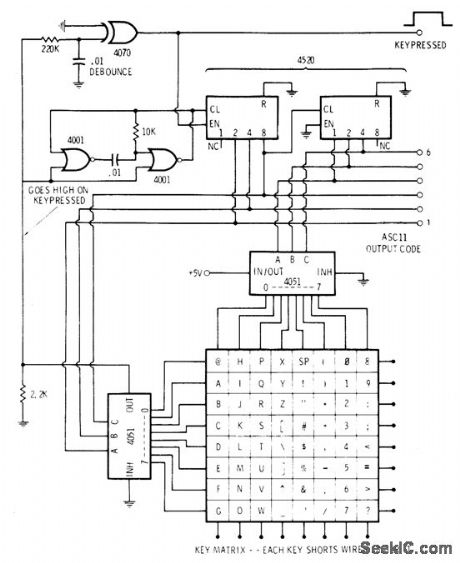
Converts key action into composite parallel ASCLL code. Circuit includes debouncing and two-key rollover. Two 4001 quad two-input NOR gate sections form 50-kHz clock that is gated. When clock is allowed to run, two cascaded 4520 binary counters are driven for continuous cycling through all their counts. Slower counter pro-duces 1-of-8 decoded output for 4051 1-of-8 switch. Faster counter drives second switch that monitors sequential rows of characters.When key is pressed, output from +5Vthrough both selectors stops gated oscillator and holds count. Resulting ASCll output is then routed to external output logic for control and shift operations. When key is released, scanning resumes and continues until new key is pressed.If second key is pressed before first is released, nothing happens until first key is released.Scanning then resumes and stops at second key location, to give two-key rollover permitting faster typing with minimum error.-D. Lancaster, CMOS Cookbook, Howard W. Sams, Indianapolis, IN, 1977, p 358-359. (View)
View full Circuit Diagram | Comments | Reading(830)
SUMMING_CHOPPING_AMPLIFIER
Published:2009/7/10 22:09:00 Author:May
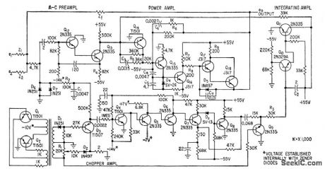
D-c operational amplioer is connected as summing amplifier with two inputs. Input-output rela-tionship is independent of ampliier charac.teristics because amplifer gcdn is sufficienlly high and effects of d.c drift in transistor circults are sufficienlly small. D-c and low-fre-quency components are amplifier in chopper amplifier and integrating ampliler, while high-frequency a-c components go through preamplifier.The two signals are combined and further boosted by power omplifier. In togretting section has time constant of 12 sec determined by C2-R3.-W. Hochwald and F.H. Gerhard, D-C Operational Amplifier With Transistor Chopper, Electronics, 32;17, p 94-96. (View)
View full Circuit Diagram | Comments | Reading(1116)
V_F_AND_F_V_CONVERTERS_FOR_DPM
Published:2009/7/10 22:08:00 Author:May
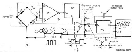
Signaltransmitted as variations in frequency in 0-10kHz range is conerted back to voltage for driving digital panel meterto give indication of temperature value sensed by 100-ohm resistive thermal device (RTD) in bridge V/Fand F/V converters can be almost any commercial modelsdes gned for 0-10 V and 0-10 kHz,Instrument amplifier can be Datel AM201 or equivalent.-E.L.Murphy,Sending Transducer Signals over 100 Feet?, lnstruments & Control Systems,June 1976, p35-39. (View)
View full Circuit Diagram | Comments | Reading(658)
POSITION_SENSOR
Published:2009/7/10 22:07:00 Author:May
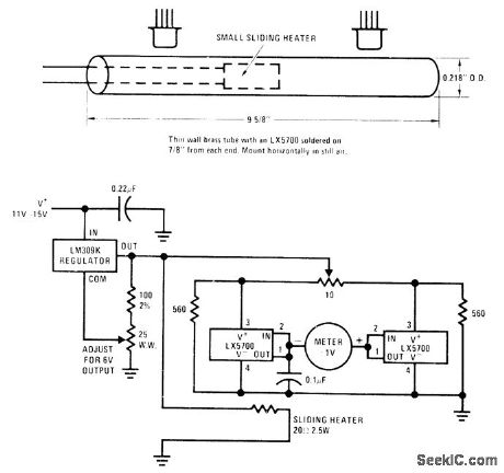
Position of small heating element sliding inside thin-wall brass tube is sensed by National LX5700 temperature transducer mounted outside of tube, With heater at center, transducers at both ends reach same temperature. With heater at one end of pipe, that transducer is about 50℃ above ambient and other is near ambient. As heater moves toward one end, one thermometer becomes more sensitive and the other less. Circuit regulates heater power to keep position gain constant. Digital voltmeter gives average position. Applications include measuring average truck spring deflection while moving on rough road.-P. Lefferts, A New Interfacing Concept; the Mono-Iithic Temperature Transducer, National Semiconductor, Santa Clara, CA, 1975, AN-132, p 9. (View)
View full Circuit Diagram | Comments | Reading(1592)
12_V_INPUT_SIMPLE_INVERTER
Published:2009/7/10 22:05:00 Author:May
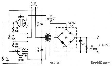
Using two power MOSFETs, this inverter can deliver ac or dc up to several hundred volts. T1 is a 12.6-V CT to 120-, 240-, or 480-V transformer for 60-Hz application. (View)
View full Circuit Diagram | Comments | Reading(1944)
125_47O_K_GIVES_125_470_Hz
Published:2009/7/10 22:05:00 Author:May
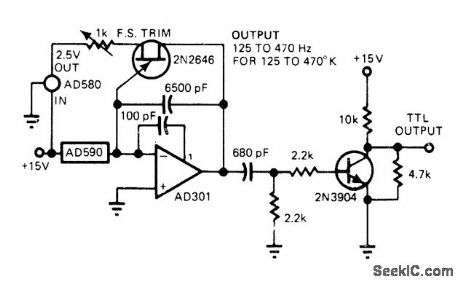
Use of AD590 current-ratioed differential-pair IC temperature transducer gives low parts count for temperature-to-frequency converter. Sensor controls AD301 opamp in relaxation oscillator, with negative-going output ramp being differentiated for driving single-transistor inverter giving TTL output.-J. Williams, Designer's Guide to: Temperature Measurement, EDN Magazine, May 20, 1977, p 71-77. (View)
View full Circuit Diagram | Comments | Reading(829)
Video_switch
Published:2009/7/17 4:42:00 Author:Jessie
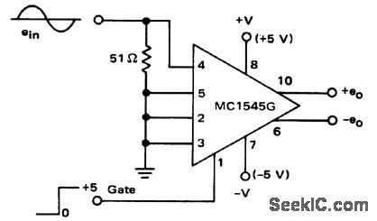
Video switch. With a logic one at pin 1 the amplifier is turned on (courtesy Motorola Semiconductor Products Inc.). (View)
View full Circuit Diagram | Comments | Reading(2390)
100_mA_TRACKING
Published:2009/7/17 4:42:00 Author:Jessie
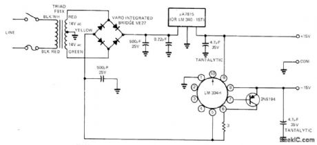
Circuit uses +15 V from μA7815 positive fixed-output regulator as external reference for LM304 negative regulator operating with outboard current-carrying PNP transistor. Arrangement requires only one center-tapped transformer winding yet gives required tracking of voltages. Output can be boosted to 200 mA by using larger bridge rectifier section.-H. Olson, Simple ±15V Regulated Supply Provides Tracking, EDN Magazine, March 20, 1973, p 87. (View)
View full Circuit Diagram | Comments | Reading(1715)
HEARTBEAT_TRANSMI_TIER
Published:2009/7/17 4:42:00 Author:Jessie
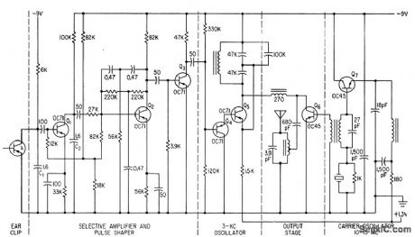
Self-contained device worn by patient transmits his pulse to radio receiver for remote monitoring or recording. Photo-transistor, fed separately, measures changes in light transmitted through earlobe as heart pulses change blood density and volume of lobe.-G. A. Horton and A K.Koroncai, Radio Transmitter for Remote Heartbeat Measurements, Electronics, 33:52, p 54-55. (View)
View full Circuit Diagram | Comments | Reading(750)
DUPLEX_AUDIO_LINK
Published:2009/7/10 22:05:00 Author:May
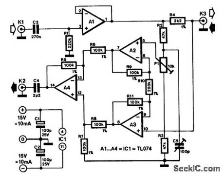
Duplex communication is, of course, not a new technique: it has been used, for instance, in telephone systems for many years. Those systems, however, use transformers to achieve duplex-this circuit does it with the aid of electronics.The principle is fairly simple. Two senders impose signals (U1 and U2, respectively) on to the audio cable. The voltage across the cable is then (U1+ U2)/2. The receivers at both sides of the cable deduct their side's sender signal from the cable signal: the result is that the signal is sent from the other end of the cable. This principle is the basis of the circuit shown. Notice that a similar circuit is required at either end of the link.Op amp A1 is connected as a buffer amplifier and serves as sender. The send signal is imposed on the cable via R4. Terminating the cable by R4 results in the voltage across the cable being only half the voltage output of A1. This does not detract from the operation of the circuit, however. At the same time, R4 ensures that signals emanating from the other end of the link cannot get to the output of A1; if they could, they would be short-cii-cuited by the output.The receiver is a differential amplifier consisting of op amps A2 through A4. The quality of the differential amplifier depends largely on the resistors used with the op amps; 1% types are, therefore, essential.The cable signal, (U1+ U2)/2, is applied to one input of the differential amplifier and the (halved) output signal of A1 to the other. Because the differential amplifier has a gain of 6 dB, the received signal applied to K2 has the same level as the original signal.The circuit is calibrated by connecting the cable to it and to its twin circuit, then injecting a 1-kHz sinusoidal signal and a 5-Vrms level to its input. The input bus of the other circuit must be short-circuited during the calibration. Adjust P2 for minimum signal at K2. Next, increase the frequency of the input signal to 10 kHz and adjust C5 for a minimum signal at K2. Repeat the procedure with the other circuit. The signal suppression at 1 kHz is of the order of 80 dB; at 20 kHz, it is approximately 60 dB.
(View)
View full Circuit Diagram | Comments | Reading(942)
ELECTRONIC_TELETYPE_KEYBOARD
Published:2009/7/10 22:04:00 Author:May
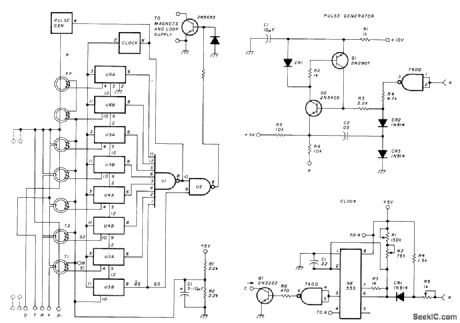
Uses eight 7474 shift register sections in combination with pulse generator that is discharged through appropriate toroid core to create correct markspace coding for energizing magnet drivers of Teletype. Developed to permit communication by handicapped people. Simplified keyboard has one set of alphabetic characters and five numeries for BCD input, Outputs of shift registers drive 7430 NAND gate U2. If keyboard is to be used at 60 WPM, adjustR1 so 555 oscillates at 45 Hz. Toroids are Indiana General CF.102 having 10-turn primaries.-L. A Stapp, Electronie Teleprinter Keyboard, Ham Radio, Aug.1978, p 56-57.
(View)
View full Circuit Diagram | Comments | Reading(1384)
| Pages:800/2234 At 20781782783784785786787788789790791792793794795796797798799800Under 20 |
Circuit Categories
power supply circuit
Amplifier Circuit
Basic Circuit
LED and Light Circuit
Sensor Circuit
Signal Processing
Electrical Equipment Circuit
Control Circuit
Remote Control Circuit
A/D-D/A Converter Circuit
Audio Circuit
Measuring and Test Circuit
Communication Circuit
Computer-Related Circuit
555 Circuit
Automotive Circuit
Repairing Circuit