
power supply circuit
Index 19
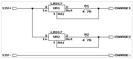
Charger schematic.
Published:2013/5/14 22:17:00 Author:muriel | Keyword: Charger schematic
View full Circuit Diagram | Comments | Reading(1171)
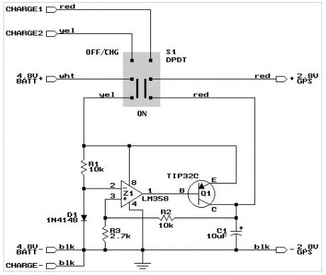
GPS mount power supply schematic.
Published:2013/5/14 22:17:00 Author:muriel | Keyword: GPS mount power supply
View full Circuit Diagram | Comments | Reading(973)
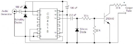
signal generator
Published:2013/5/9 21:42:00 Author:muriel | Keyword: signal generator
View full Circuit Diagram | Comments | Reading(1715)
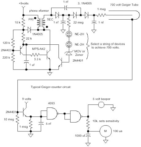
3 Volt Geiger Counter Power Supply
Published:2013/5/9 21:40:00 Author:muriel | Keyword: 3 Volt , Geiger Counter , Power Supply
View full Circuit Diagram | Comments | Reading(1725)
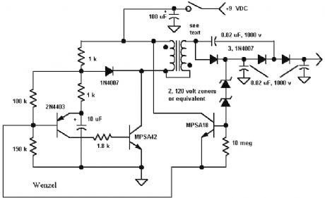
9 Volt Geiger Counter Power Supply
Published:2013/5/9 21:39:00 Author:muriel | Keyword: 9 Volt , Geiger Counter, Power Supply
View full Circuit Diagram | Comments | Reading(2099)
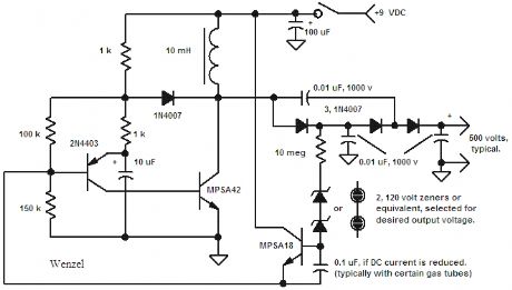
500 Volt Geiger Counter Power Supply
Published:2013/5/9 21:39:00 Author:muriel | Keyword: 500 Volt, Geiger Counter , Power Supply
View full Circuit Diagram | Comments | Reading(1242)
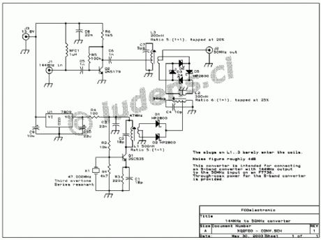
144MHz to 50MHz receive converter
Published:2013/5/9 21:18:00 Author:muriel | Keyword: 144MHz to 50MHz , receive converter
View full Circuit Diagram | Comments | Reading(1266)
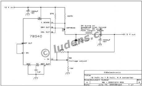
The glow plug converter: 12V to 1.5V, at 4A
Published:2013/5/9 21:07:00 Author:muriel | Keyword: The glow plug converter, 12V to 1.5V, 4A
View full Circuit Diagram | Comments | Reading(1707)
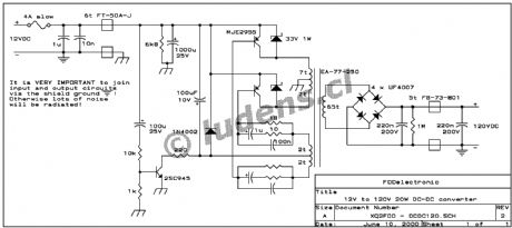
The VCR converter: 12V to 120V, 20 Watt
Published:2013/5/9 21:07:00 Author:muriel | Keyword: The VCR converter, 12V to 120V, 20 Watt
View full Circuit Diagram | Comments | Reading(1464)
12V input, 12V battery charger 2
Published:2013/5/7 22:08:00 Author:muriel | Keyword: 12V input, 12V , battery charger
View full Circuit Diagram | Comments | Reading(1094)
DC-DC converters
Published:2013/5/7 22:08:00 Author:muriel | Keyword: DC-DC converters

View full Circuit Diagram | Comments | Reading(1883)
13.8V 20A linear power supply
Published:2013/5/7 22:06:00 Author:muriel | Keyword: 13.8V , 20A , linear power supply
View full Circuit Diagram | Comments | Reading(2868)
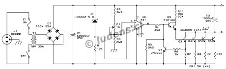
10A CAR BATTERY CHARGER
Published:2013/5/7 21:25:00 Author:muriel | Keyword: 10A , CAR BATTERY CHARGER

The charger is suitable for lead-acid car batteries and it is assembled in two units: a metal box with the toroidal transformer, instrument, lights, etc, and a small plastic box housing the voltage and temperature circuit. Connection between main box and sensor is realized with a standard 3 core x 1mm, electric cable, 4m long. Its resistance is factored in the circuit calculations and it is the limiting resistor against overcurrent. Do not change type or length as it may alter the overall performance and safety of the charger. The sensor box is typically positioned close to the battery to be charged and two short flexible leads, 2mm section, 30cm long, one red and black the other, terminated with good quality clamps make up the connection from the sensor to the battery.
This solution assures that the battery is charged up to the correct voltage which depends, in turn, upon the ambient temperature. The final voltage should be set, with the 200Ω multiturn pot, at 14.8V at 20°C-68°F and derated +/-30mV/°C (17mV/°F) at any other temperature. For example, if the prevailing ambient temperature is 10°C then the final voltage should be set at 15.1V, if the prevailing ambient temperature is 30°C the final voltage is 14.5V and so on. Once set, the circuit will automatically adjust the voltage to within 1°C. You have to connect a battery in order to carry out this setting.
A thermistor would have simplified the circuit but its correct implementation is not easy and it was preferred to employ a number of diodes. A red led in the sensor box gives an indication of the correct connection to the battery. However the circuit is quite tolerant to mistakes: shorting the output will do no arm as there is no voltage at the output terminals, not until you connect it to the battery. It is the battery voltage that triggers the circuit into operation and once it is disconnected from the battery the voltage too disappears from the output. Only if the battery voltage is above 7-8V then the circuit will operate. A reverse connection of any battery will do no arm either as the circuit will simply not operate. It will withstand a temporary connection of a 24V battery; above this voltage the input circuit is overloaded and could be damaged.
Current control is achieved by switching the SCRs at the appropriate time through the BF761 collector current. The blue led, but any other colour will do, gives an indication that the unit is charging the battery. The led will start flickering at the end of the charging cycle so you know at a glance that the charge is coming to an end. You may leave the battery connected after it has fully charged as there will be a trickle charge which will keep the voltage at its optimum level. Switching noise is eliminated by the 85μH choke made up by winding 27 turns of 1mm enamelled wire on a ferrite ring 27x11mm. Due to the way SCRs operate, the common line is positive and not negative as one would expect. Care must be exercised when connecting all the polarity sensitive devices.
A toroidal transformer has many advantages: it is small, highly efficient, will tolerate a moderate overload and will consume little power, only 3.5VA when switched on and no battery connected. Cost, at this power range, is surprisingly close to a traditional transformer, yet, the inrush current when switched on can be so high, depending on the exact time with respect to the mains sinewave, that the collapse of the ensuing strong magnetic field will produce mighty spikes up to 500V at the secondary, destroying whatever they find in their path. A few capacitors, the use of fast diodes UF4006 and the high voltage transistor BF761 take care of the problem. The main switch should be rated at 10A.
SCRs can get rather hot; the best solution is to mount them on the metal case itself using appropriate insulating kits. As a consequence the box will warm up especially at the beginning of the charging cycle when the unit may be temporarily overloaded. A thermal switch is provided to cut out the mains supply under extreme temperature and overload conditions. This switch is mounted at about 6-8cm away from the SCRs so that it will take care of the heat coming from other sources as well, such as the transformer and the choke.
The unit has been tested with batteries from 44 to 100Ah for over a year, from 0 to 38°C (32 to 100°F); the upper temperature limit caused the thermal switch to operate. I should relocate the thermal switch in a cooler place if the designed max operating temperature of 40°C-104°F is to be met. You may have different temperature limits depending on the mechanical configuration of the box and internal components layout. Pay attention to the fact that this charger behaves like a fast charger for the smaller batteries and precautions should be taken concerning gas production and it is good practice to disconnect the battery from the car before charging it. (View)
View full Circuit Diagram | Comments | Reading(3703)
ALKALINE CHARGER
Published:2013/5/7 21:20:00 Author:muriel | Keyword: ALKALINE CHARGER
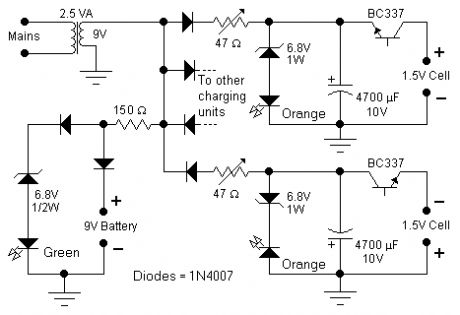
This circuit was specifically designed to recharge alkaline cells. The unusual connection of the transistor in each charging unit will cause it to oscillate, on and off, thus transferring the charge accumulated in the capacitor to the cell. The orange LED will blink for around 5 times a second for a 1.37V cell. For a totally discharged cell the blinking is faster but it will decrease until it will come to a stop when the cell is charged. You may leave the cell in the charger as it will trickle charge and keep it at around 1.6V. To set the correct voltage you have to connect a fresh, unused cell and adjust the trimmer until oscillations set in, then go back a little until no oscillation is present and the circuit is ready to operate. You should use only the specified transistors, LED colors, zener voltage and power rating because they will set the final voltage across the cell. A simple 9V charging circuit was also included: it will charge up to around 9.3V and then keep it on a trickle charge: the green LED will be off while charging and will be fully on when the battery is close to its final voltage.
A 2.5VA transformer will easily charge up to 4 cells at the same time although 2 only are shown in the schematic. In order to minimize interference from one circuit to the other they have nothing in common except the transformer and, in order to show a balanced load to the transformer, half of the charging units will use the positive sinewave and the other half the negative sinewave. Make sure to use high beta transistors such as BC337-25 or better BC337-40. Given the dispersion of the transistor parameters it might happen that oscillations do not take place. Use a slightly higher zener voltage: 7.5V instead of 6.8 or a green led in place of the orange ones.
All types of alkaline cells can be recharged: it will take 1 day for a discharged AA cell or 9V battery and up to several days for a large D type cell. The best practice is not to discharge completely the cell or battery but rather to give a short charge every so often although admittedly this is not easy to achieve. Do not attempt to recharge a totally discharged cell or a cell showing even the slightest sign of damage.
I tried successfully to recharge NiMH cells as well. Although the charging profile for these cells is quite different from alkaline cells, the circuit seems to work fine provided you do not leave them in the charger forever, because of the possibility of overcharging especially for the smaller batteries.
The mains transformer must be suited for the voltage available in each country: usually 230Vac or 115Vac. (View)
View full Circuit Diagram | Comments | Reading(1278)
HIGH VOLTAGE GENERATOR
Published:2013/5/7 21:13:00 Author:muriel | Keyword: HIGH VOLTAGE GENERATOR
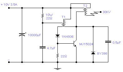
Easy to build, this high voltage generator is capable of generating up to 50KV but the breakdown voltage of the coil limits the voltage to a value somewhat lower. T2 is the ignition coil of a car and also the 0.5µF capacitor comes from the same place: actually I suggest using only this type of capacitor. T1 is a small transformer with a laminated iron rod, with a square section of 7x7mm, 57mm long with 75 turns on the collector side and 25 turns on the base side made with a 1mm enamelled wire. Its implementation is not critical and I expect that the circuit will work with a wide variety of transformers including ferrite ones. Try to invert one of the windings if the circuit does not oscillate. The transistor will stay quite cool and does not require a radiator if it is assembled on a metal case; otherwise a small 5ºC/W radiator will suffice. Frequency of operation is around 1.2KHz. (View)
View full Circuit Diagram | Comments | Reading(0)
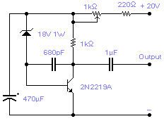
NOISE GENERATOR
Published:2013/5/7 21:11:00 Author:muriel | Keyword: NOISE GENERATOR
View full Circuit Diagram | Comments | Reading(4301)
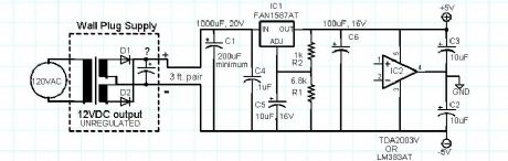
a balanced power supply for mixed analog-digitial circuits
Published:2013/5/7 20:52:00 Author:muriel | Keyword: balanced power supply, mixed analog-digitial circuits
View full Circuit Diagram | Comments | Reading(1101)
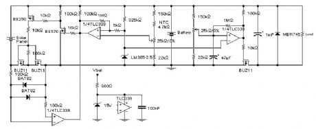
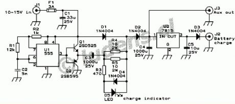
Solar charger for lead-acid batteries 2
Published:2013/5/2 22:13:00 Author:muriel | Keyword: Solar charger, lead-acid batteries
View full Circuit Diagram | Comments | Reading(3034)
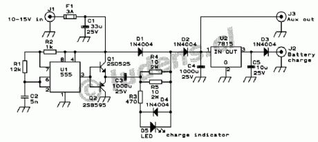
12V battery charger with 12V input
Published:2013/5/2 22:12:00 Author:muriel | Keyword: 12V battery charger, 12V input
View full Circuit Diagram | Comments | Reading(2570)
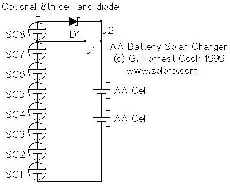
AA Battery Solar Charger
Published:2013/5/2 21:38:00 Author:muriel | Keyword: AA Battery , Solar Charger
View full Circuit Diagram | Comments | Reading(1614)
| Pages:19/291 1234567891011121314151617181920Under 20 |
Circuit Categories
power supply circuit
Amplifier Circuit
Basic Circuit
LED and Light Circuit
Sensor Circuit
Signal Processing
Electrical Equipment Circuit
Control Circuit
Remote Control Circuit
A/D-D/A Converter Circuit
Audio Circuit
Measuring and Test Circuit
Communication Circuit
Computer-Related Circuit
555 Circuit
Automotive Circuit
Repairing Circuit