
power supply circuit
Index 18
DCC To DC - Accessory Power Supplies
Published:2013/6/13 21:22:00 Author:muriel | Keyword: DCC To DC , Accessory Power Supplies
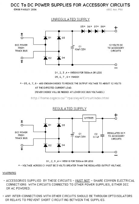
These circuits can be used to supply low current DC accessory circuits by tapping into the DCC track supply Bus. This might be done if a regular DC supply was not available and the power required by the accessory was small.
The unregulated power supply circuit could be used to supply power to the Automatic Grade Crossing circuit on this site.
WARNING - Accessories supplied by these circuits must not share common electrical connections with circuits connected to other power supplies, either DCC or AC powered. Any inter-connections with other circuits should be through optoisolators or relays to prevent possible short-circuiting between the supplies. (View)
View full Circuit Diagram | Comments | Reading(1244)
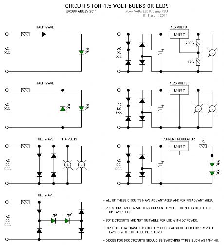
Low Voltage Power Supplies For LEDs Or Lamps
Published:2013/6/13 1:37:00 Author:muriel | Keyword: Low Voltage, Power Supplies, LEDs , Lamps
View full Circuit Diagram | Comments | Reading(1149)
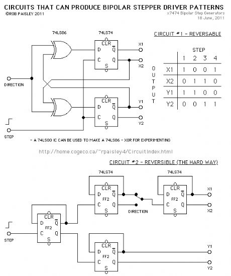
7474 Bipolar Stepper Driver Generators
Published:2013/6/13 1:27:00 Author:muriel | Keyword: 7474, Bipolar, Stepper Driver, Generators
View full Circuit Diagram | Comments | Reading(1392)
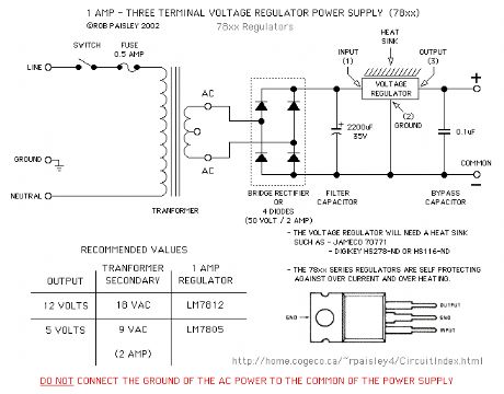
Fixed Voltage Regulators 5 Or 12 Volt Supply
Published:2013/6/7 21:21:00 Author:muriel | Keyword: Fixed Voltage Regulators, 5 Or 12 Volt Supply
View full Circuit Diagram | Comments | Reading(1186)
Throttle Power Supply
Published:2013/6/7 21:20:00 Author:muriel | Keyword: Throttle Power Supply
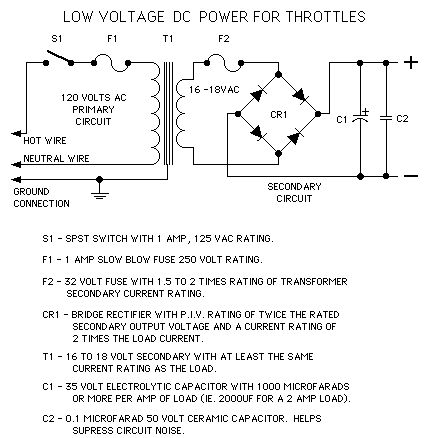
The first schematic is of the Direct Current power supply for the throttles. Shown is the primary and secondary circuits and the components needed to power the throttles. As this section of the throttles uses 120 volt AC power great caution should be taken in this area. All transformers should be mounted in a fully enclosed metal cabinet and properly grounded. Transformers for multiple units could be centrally located and the low voltage AC then routed to each throttle.
(View)
View full Circuit Diagram | Comments | Reading(1069)
A Power Supply For Use With Transistors
Published:2013/6/6 20:38:00 Author:muriel | Keyword: Power Supply , Transistors
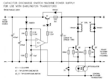
The circuit is a variation of the SCR compatible power supply. This version can be used if transistors were used to control switch machines.
The only significant differences between this and the SCR compatible circuit is the removal of the time delay before recharging begins and the higher control current that would be required for transistors as opposed to silicon controlled rectifiers.
As with the SCR compatible circuit this version cannot be used with pushbuttons in the coil circuit as the charging current would not be cutoff when the button is pushed. (View)
View full Circuit Diagram | Comments | Reading(1296)
A Power Supply For Use With Silicon Controlled Rectifiers
Published:2013/6/6 20:37:00 Author:muriel | Keyword: Power Supply , Silicon Controlled Rectifiers
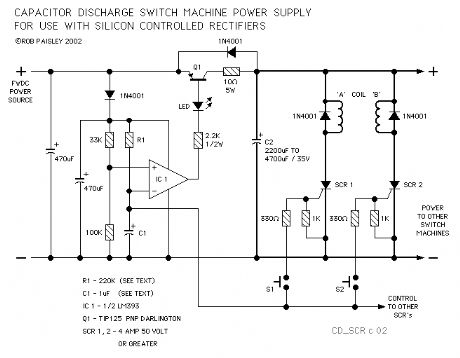
The next power supply is designed specifically for use with silicon controlled rectifiers. The SCR's would take the place of push buttons in the high current paths of the switch machine control circuits.
These devices are ideally suited for use where large current surges are expected and in many cases they are less expensive than darlington transistors. (View)
View full Circuit Diagram | Comments | Reading(1722)
Split Supply - Current Blocking Switch Machine Power Supply
Published:2013/6/6 20:37:00 Author:muriel | Keyword: Split Supply , Current Blocking , Switch Machine , Power Supply
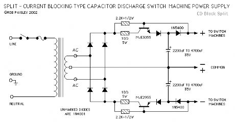
The next circuit is essentially the same as the one above except that a split of dual output is provided. The circuit therefore has a PLUS, MINUS and NEUTRAL output terminal but functions in the same manner as the single sided power supply circuit.
A 1N4001 diode has been placed in the emitter circuit of the power transistors to ensure that the proper voltage differential is achieved between the base and emitter junctions of these transistors.
This circuit has not been tested on a layout but should work as designed. Please take some time to experiment before actually installing the circuit. (View)
View full Circuit Diagram | Comments | Reading(1716)
Current Blocking Switch Machine Power Supply
Published:2013/6/6 20:36:00 Author:muriel | Keyword: Current Blocking , Switch Machine, Power Supply
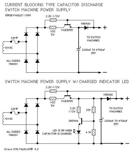
The Current Blocking type of switch machine supply is a widely used device and is well documented. It is reliable and practical design.
Simply stated; This type of supply blocks the charging current to the storage capacitor anytime current is flowing from the output of the circuit, such as when a switch machine is activated.
The only modification that this circuit might use is: (1) A resistor to limit the maximum charging current to a reasonable level. (2) a Capacitor Charged indicator. These additions are shown on the next diagram.
The first schematic on the following diagram shows a current blocking switch machine power supply with a 10 ohm resistor in the collector circuit of the blocking transistor. This resistor should be a wire wound type power resistor as it will have to handle peak currents of approximately 2.4 amps.
The second schematic shows a Capacitor Charged indicator added to the circuit. The LED will begin to glow when the voltage across the capacitor is approximately 16 volts and be fully lit at about 20 volts. (View)
View full Circuit Diagram | Comments | Reading(1370)
Simple But Effective Switch Machine Power Supply
Published:2013/6/6 20:35:00 Author:muriel | Keyword: Simple , Effective, Switch Machine, Power Supply
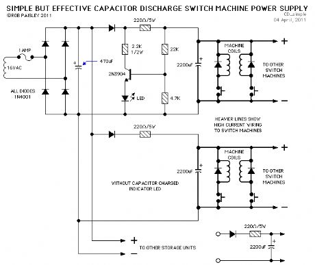
The first circuit of this page is for a classic Resistor / Capacitor unit but with a few modifications made.
The standard bugaboo with this type of circuit is the relatively long charging time of the capacitor. But if you are willing to wait the 1 second that a 2200uF capacitor takes to charge to 90 percent of its maximum voltage when a 220 ohm resistor is used this can be a simple and cost effective power supply. Using a lower resistance charging will shorten the charging time proportionally.
Shown in the top power supply circuit is an indicator circuit that shows when the capacitor is near its full charge. This is an optional feature and can be left out as shown on the second unit.
To increase the availability of switch machine power more than one discharge unit can be connected to a central transformer and rectifier / filter capacitor. This would allow smaller discharge units to be placed around the layout and used to operate machines that are nearby.
The diode in front of the 220 ohm resistor will prevent units from draining the voltage from each other when turnouts are thrown. Although this is unlikely to happen with an adequately sized supply transformer.
If the recharging time is not too important such as for machines that are not thrown often, the value or the 220 ohm resistor could be increased and its wattage reduced. The maximum potential load on the circuit will be reduced accordingly. If not as much pulse current is needed to throw the turnouts then the value of the capacitor could also be reduced.
With a 16 volt AC supply transformer the DC voltage across the capacitor will be about 21 volts and the maximum charging current will be 0.2 amps.
For a circuit of this type the charging time is dependent on the values of the resistor and capacitor used. For example if a 220 ohm resistor and a 2,200 microfarad capacitor are used then the charging time constant would be as follows.
220 Ohms X 2,200uf = 0.484 Seconds (1 Time Constant)
This is the time that the capacitor would take to reach 63 percent of the supply voltage. The time needed to reach approximately 88 percent of the supply voltage is 2 time constants.
2 X 0.484 = 0.986 Seconds (2 Time Constants)
For practical purposes the time to reach the supply voltage is 5 time constants.
If you have a little patience, about one second's worth, the basic resistor / capacitor power supply can be a very effective and economical system. However if you have the need for speed then one of the more sophisticated supplies is required. (View)
View full Circuit Diagram | Comments | Reading(1255)
Basic Twin Coil Switch Machine Power Supplies
Published:2013/6/6 20:35:00 Author:muriel | Keyword: Basic Twin Coil, Switch Machine, Power Supplies
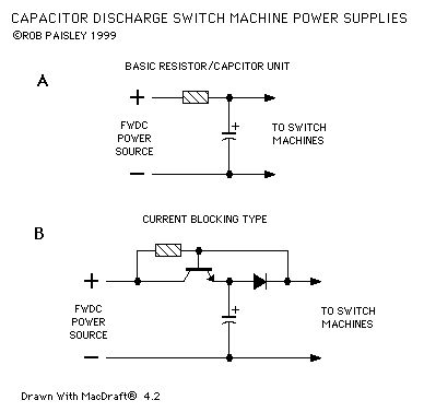
The following diagram shows two basic twin coil switch machine power supplies.
Circuit A is the simplest type but suffers from a relatively slow recovery rate.
Circuit B is a very popular power supply as it has a very good recovery time. This circuit has a high current surge when the capacitor is charging. (View)
View full Circuit Diagram | Comments | Reading(1303)
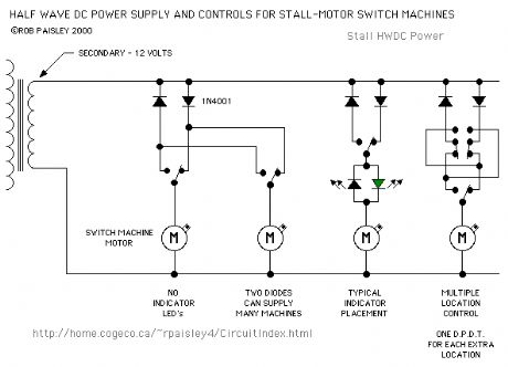
Half Wave DC - Stall Motor Switch Machine Power Supply
Published:2013/6/5 21:27:00 Author:muriel | Keyword: Half Wave DC , Stall Motor , Switch Machine, Power Supply
View full Circuit Diagram | Comments | Reading(1025)
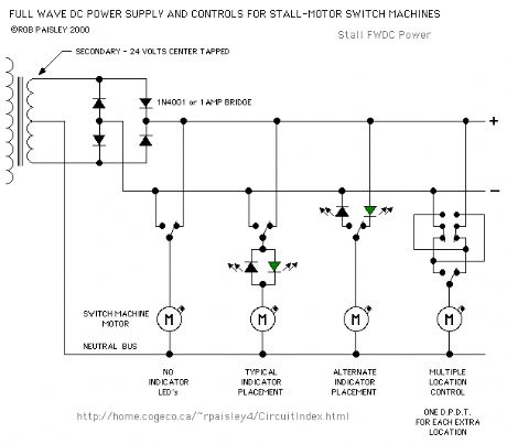
Full Wave DC - Stall Motor Switch Machine Power Supply
Published:2013/6/5 21:27:00 Author:muriel | Keyword: Full Wave DC , Stall Motor Switch, Machine Power Supply
View full Circuit Diagram | Comments | Reading(959)
1.5 Volt Power Supply schematic
Published:2013/5/31 1:55:00 Author:muriel | Keyword: 1.5 Volt, Power Supply schematic

View full Circuit Diagram | Comments | Reading(2375)
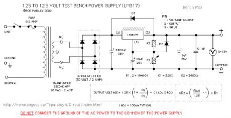
Test Bench Power Supply Schematic
Published:2013/5/31 1:54:00 Author:muriel | Keyword: Test Bench Power Supply Schematic

View full Circuit Diagram | Comments | Reading(1680)
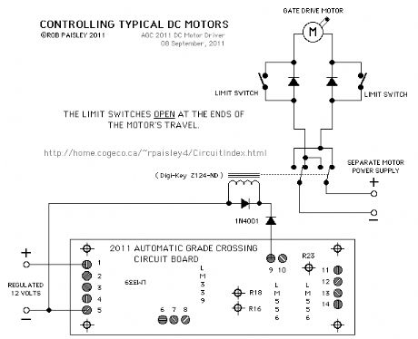
motor's power circuit
Published:2013/5/28 22:00:00 Author:muriel | Keyword: motor's power circuit
View full Circuit Diagram | Comments | Reading(0)
Alternate Power Supplies For the Meter
Published:2013/5/22 22:24:00 Author:muriel | Keyword: Alternate Power Supplies, the Meter
View full Circuit Diagram | Comments | Reading(1068)
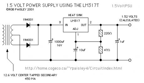
1.5 Volt Power Supply - LM317
Published:2013/5/16 1:59:00 Author:muriel | Keyword: 1.5 Volt, Power Supply , LM317
View full Circuit Diagram | Comments | Reading(2836)
A Test Bench Power Supply
Published:2013/5/16 1:59:00 Author:muriel | Keyword: Test Bench Power Supply
View full Circuit Diagram | Comments | Reading(1274)
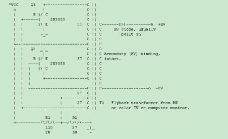
HV supply: 12VDC in, 12KV out
Published:2013/5/16 1:51:00 Author:muriel | Keyword: HV supply, 12VDC in, 12KV out
View full Circuit Diagram | Comments | Reading(1115)
| Pages:18/291 1234567891011121314151617181920Under 20 |
Circuit Categories
power supply circuit
Amplifier Circuit
Basic Circuit
LED and Light Circuit
Sensor Circuit
Signal Processing
Electrical Equipment Circuit
Control Circuit
Remote Control Circuit
A/D-D/A Converter Circuit
Audio Circuit
Measuring and Test Circuit
Communication Circuit
Computer-Related Circuit
555 Circuit
Automotive Circuit
Repairing Circuit