
power supply circuit
Index 14
Regal external modulation circuit diagram
Published:2013/12/13 2:02:00 Author: | Keyword: Regal external modulation circuit diagram ,
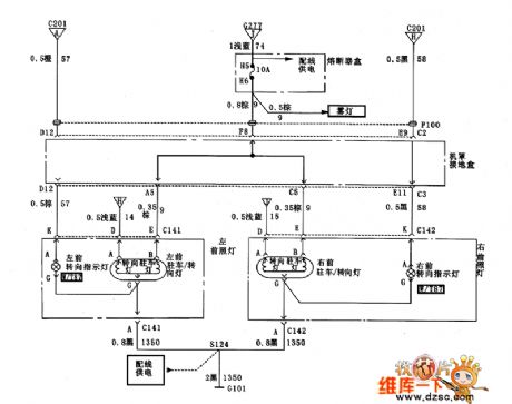
Figure regal external modulation circuit diagram (View)
View full Circuit Diagram | Comments | Reading(871)
Regal body internal light XiaoGuang light circuit diagram
Published:2013/12/13 1:59:00 Author: | Keyword: Regal body internal light XiaoGuang light circuit diagram,
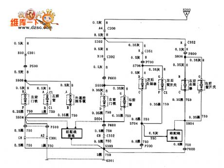
Figure regal body internal light XiaoGuang light circuit diagram (View)
View full Circuit Diagram | Comments | Reading(847)
Principle of non-isolated switching power supply are three basic ways of working circuit
Published:2013/12/12 20:20:00 Author:lynne | Keyword: Principle of non-isolated switching power supply are three basic ways of working circuit,
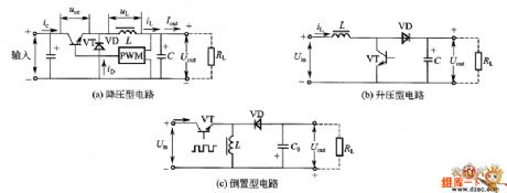
Principle of non-isolated switching power supply are three basic ways of working circuit shown in Figure:
(View)
View full Circuit Diagram | Comments | Reading(1298)
Regal Charging System Diagram
Published:2013/12/12 2:31:00 Author: | Keyword: Regal Charging System Diagram,
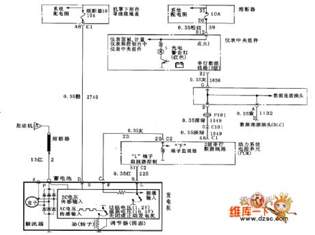
Figure regal charging system circuit diagram (View)
View full Circuit Diagram | Comments | Reading(866)
Regal Start System Diagram
Published:2013/12/12 2:30:00 Author: | Keyword: Regal Start System Diagram,

Figure regal startup system circuit diagram (View)
View full Circuit Diagram | Comments | Reading(811)
Regal headlight circuit diagram 2
Published:2013/12/12 2:29:00 Author: | Keyword: Regal headlight circuit diagram 2,
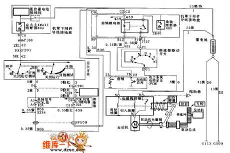
Figure regal headlamps circuit diagram 2 (View)
View full Circuit Diagram | Comments | Reading(1262)
Based 12v sealed lead acid battery charger circuit diagram dual level float
Published:2013/12/12 2:27:00 Author: | Keyword: Based 12v sealed lead acid battery charger circuit diagram dual level float,
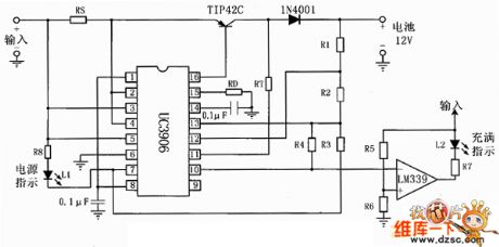
12v sealed lead acid battery based on bi-level float charger circuit is shown below:
(View)
View full Circuit Diagram | Comments | Reading(3046)
Automatic circuit diagram based on lead-acid rechargeable
Published:2013/12/12 2:26:00 Author: | Keyword: Automatic circuit diagram based on lead-acid rechargeable,
Lead-based automatic charging circuit is shown below:
(View)
View full Circuit Diagram | Comments | Reading(2289)
Counter chip of cadmium nickel battery charger circuit diagram
Published:2013/12/11 1:36:00 Author: | Keyword: Counter chip of cadmium nickel battery charger circuit diagram, CD4040
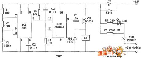
Ni-Cd battery charger counter chip composed as shown. It can 500mA capacity of four nickel-cadmium batteries in series , the charging current is 50mA, the charging time is l.5 hours after charging is complete and has automatic power-off function. 555 circuit clock signal generator generates a square wave signal l0Hz , the period of 6 seconds. When the power is turned on , because of IC2 ③ pin output low , thus making semiconductor VT1 conduction, and to pull the relay Kl work contacts K1-1 is closed, the switch S is self-preservation. In this case the charging current flows to the battery and charging the battery starts . Status indicator LED is lit, it indicates charging is in progress. CD4040 counter constitute divider and charging circuit . While the power is turned on , the clock signal generated by ICl lost ⑩ feet of IC2 , IC2 starts counting. Since IC2 is connected to a 8192:1 divider , so only counts when you reach 8192 feet of IC2 ③ only from low to high , so VTl deadline , Kl stop working and release contact K1-1, so that it becomes the OFF state to stop the charging. VD2 is used to prevent the battery current from flowing back into the circuit.
(View)
View full Circuit Diagram | Comments | Reading(1088)
Phone charger power conversion circuit diagrams
Published:2013/12/11 1:46:00 Author: | Keyword: Phone charger power conversion circuit diagrams,
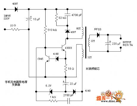
Phone charger power conversion circuit is shown below:
(View)
View full Circuit Diagram | Comments | Reading(1382)
12V lead-acid battery charging circuit diagram
Published:2013/12/11 1:45:00 Author: | Keyword: 12V lead-acid battery charging circuit diagram,
12V lead-acid battery charging circuit is shown below:
(View)
View full Circuit Diagram | Comments | Reading(1550)
Strong reliability pocket charger switching power supply circuit diagram
Published:2013/12/11 1:40:00 Author: | Keyword: Strong reliability pocket charger switching power supply circuit diagram,

Strong reliability pocket charger switching power supply circuit as shown below:
(View)
View full Circuit Diagram | Comments | Reading(1130)
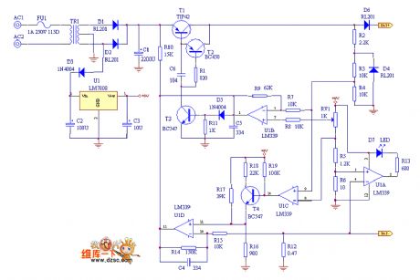
After the first release with features nickel-cadmium rechargeable battery charger circuit diagram
Published:2013/12/10 1:36:00 Author: | Keyword: After the first release with features nickel-cadmium rechargeable battery charger circuit diagram,
The first circuit for nickel-cadmium battery discharge before charging to eliminate memory effect, After discharge automatically converted to the charging state. Charging way width modulation constant flow, constant current charge plus pulsating pulse discharge, the voltage across the battery full detection, and implement dual control, parallel charging, with anti-reverse charging function.
(View)
View full Circuit Diagram | Comments | Reading(1353)
Ni-Cd battery charger circuit diagram of timing
Published:2013/12/10 1:35:00 Author: | Keyword: Ni-Cd battery charger circuit diagram of timing,
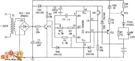
The circuit is a timed charger, charging time can be within 5 to 25 hours to adjust the charging process, such as a power outage, the circuit has accumulated timing function. This circuit can be on the 5th nickel-cadmium batteries.
(View)
View full Circuit Diagram | Comments | Reading(1364)
Sealed lead-acid battery charging circuit diagram
Published:2013/12/10 1:33:00 Author: | Keyword: Sealed lead-acid battery charging circuit diagram,

As shown in FIG. It can l just once or two 6V, 4Ah battery charging. Regulators part adopts switching power supply module TWH9312, wide input voltage range; interior also features over-current, short circuit protection, safe and reliable.
(View)
View full Circuit Diagram | Comments | Reading(1462)
Solar Charger Monitor Circuits
Published:2013/12/5 19:56:00 Author:lynne | Keyword: Solar Charger Monitor Circuits
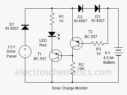
This add on circuit can be attached to the solar charger to see whether the battery is charging or not. It lights a Red LED to indicate that the battery is not accepting charge. It gives a warning indication if there is any loose connection with the charger and battery.
The Solar charger monitor circuit uses two PNP transistors T1 and T2 to give a warning indication if there is any loose connection with the charger and battery. If the connection is intact and current is flowing into the battery, diodes D2 and D3 forward bias and drops around 1.2 volts. This forward voltage drop across the diodes causes T2 to conducts. The collector current from T2 keeps the base of T1 high and it remains off. Red LED connected to the emitter of T1 remains off indicating that current is flowing to the battery and the connections are intact. When there is any break in the connecting cables or any loose contacts in the terminals, no more current passes and D2 and D3 reverse biases. This turns off T2 and T1 conducts .LED lights indicating that battery is not getting charging current.
Solar Charger Monitor Circuit Diagram
(View)
View full Circuit Diagram | Comments | Reading(1361)
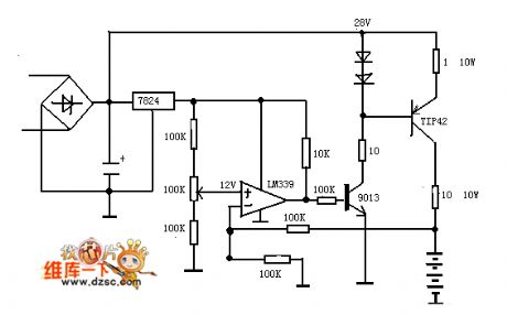
Battery Monitor Circuits
Published:2013/12/5 19:47:00 Author:lynne | Keyword: Battery Monitor Circuit
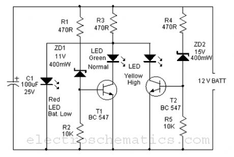
Here is a simple Battery Monitor circuit for a quick check of 12 volt Lead-Acid Battery. Battery charge should be constantly monitored to increase the life of the battery. Overcharge as well as under charge will reduce the battery life. The terminal voltage of the Lead Acid battery should be with in the range of 12.5 to 13.5 volts. If the battery voltage reduces below 10 volts for long period, battery will not accept any charging current. Similarly if the terminal voltage exceeds above 14 volts, battery will be destroyed.
The circuit is a Zener controlled transistor switch lighting three LEDs Red, Green and Yellow to show battery states like Low, Normal and High. When the battery voltage is less than 11 volts, Zener diodes ZD1 and ZD2 cease to conduct and Red LED only lights indicating low battery condition. If the voltage is between 12 volt and 14 volts, Zener diode ZD1 forward bias and T1 conducts. The Green LED connected to the collector of T1 lights indicating normal voltage. If the battery voltage exceeds 15 volts, Zener diode ZD2 also conducts and T2 forward bias. This lights Yellow LED indicating over charge. Thus the following indications can be obtained.
Battery Monitor Circuit Diagram (View)
View full Circuit Diagram | Comments | Reading(1963)
Simple Battery Monitor Circuits
Published:2013/12/5 19:43:00 Author:lynne | Keyword: Simple Battery Monitor Circuits

This simple Battery Monitor lights an LED when the battery voltage drops below 9 volts. It is an ideal add on circuit to monitor the charge level in 12 volt miniature batteries used in Portable devices or Alarm systems. In the standby state, LED remains off.
Working of the circuit is based on the base biasing of transistor T1. When the battery voltage is above 9 volts, base-emitter voltage will be same. This keeps both T1 and LED off. When the battery voltage reduces below 9 volts due to consumption, base voltage of T1 drops while its emitter voltage remains same since capacitor C1 is fully charged. At this stage, base of T1 becomes positive and T1 turns on. Capacitor C1 discharges through the LED and it lights.
Simple Battery Monitor Circuit (View)
View full Circuit Diagram | Comments | Reading(1062)
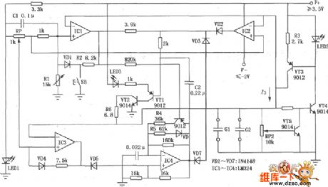
Battery Level Monitor Circuits
Published:2013/12/4 21:39:00 Author:lynne | Keyword: Battery Level Monitor Circuit
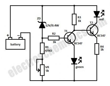
This simple battery level monitor circuit can indicate the charging process in 12 Volt Lead Acid battery or Tubular battery. The status of LED indicates whether the battery is accepting charge or not. It also indicates the full charge condition.
The battery monitor circuit can be incorporated in any battery charger like 6, 9, 12 volt etc. The only change needed is replacement of the Zener ZD with appropriate value. That is for 6 volt charger use 6.1 volt Zener and for 9 volt charger it should be 9.1 volt Zener.
Battery Level Monitor Circuit
The circuit is based on the switching of two NPN transistors (BC547) to drive the corresponding LED. Zener diode ZD is connected to the base of T1 so as to switch on T1 when the Zener conducts. This happens only when the battery voltage is above 12 volts. Green LED lights when the battery voltage is normal or battery attains full charge. Resistor R1 and Preset VR adjust the base bias of T1 for smooth switching. When T1 conducts, base of T2 will be pulled to ground and T2 turns off and Red LED extinguishes.
When is connected to the battery before charging the LED indications will be
If the battery voltage is above 12 volts (that is the normal terminal voltage of 13.8), Zener conducts and Green LED lights and Red LED remains off.If the battery voltage is below 12 volts, Zener remains non conducting and Green LED remains off and Red LED lights.When the battery is connected to the charger, and if the battery is accepting charge, Green LED goes off and Red LED remains on. When the battery attains full charge, Green LED lights and Red LED goes off. If the battery is not accepting charge, Green LED never lights, even after the prolonged charging. This indicates that the battery is not attaining the normal terminal voltage above 12 volts. (View)
View full Circuit Diagram | Comments | Reading(2347)
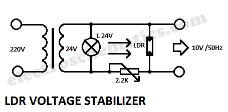
Voltage Stabilizer Circuits with LDR (Photoresistor)
Published:2013/12/4 21:28:00 Author:lynne | Keyword: Voltage Stabilizer Circuit with LDR (Photoresistor)
Voltage Stabilizer Circuit with LDR (Photoresistor)
This is a very interesting a.c. voltage stabilizer that uses a LDR or photoresistor to stabilize an alternating current (AC).If the voltage increases then the brightness of the light bulb increases too and the LDR’s resistance will decrease. If the potentiometer is properly adjusted then the AC voltage will stay constant.
The optimal adjustment of potentiometer is done experimental, feeding the circuit with a variable ratio transformer, which can simulate variations of voltage network.
LDR voltage stabilizer circuit schematic
(View)
View full Circuit Diagram | Comments | Reading(1176)
| Pages:14/291 1234567891011121314151617181920Under 20 |
Circuit Categories
power supply circuit
Amplifier Circuit
Basic Circuit
LED and Light Circuit
Sensor Circuit
Signal Processing
Electrical Equipment Circuit
Control Circuit
Remote Control Circuit
A/D-D/A Converter Circuit
Audio Circuit
Measuring and Test Circuit
Communication Circuit
Computer-Related Circuit
555 Circuit
Automotive Circuit
Repairing Circuit