
power supply circuit
Index 4
Universal jinbei Portland auto electric Windows after the circuit diagram
Published:2014/3/4 20:32:00 Author: | Keyword: Universal jinbei Portland auto electric Windows after the circuit diagram,
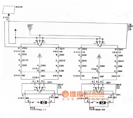
As shown in this universal jinbei Portland auto electric Windows after the circuit diagram (View)
View full Circuit Diagram | Comments | Reading(1308)
Automatic battery charger circuit diagram
Published:2014/3/4 20:18:00 Author:lynne | Keyword: Automatic battery charger circuit diagram,
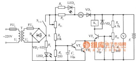
As shown in Fig automatic battery charger circuit diagram:
(View)
View full Circuit Diagram | Comments | Reading(2478)
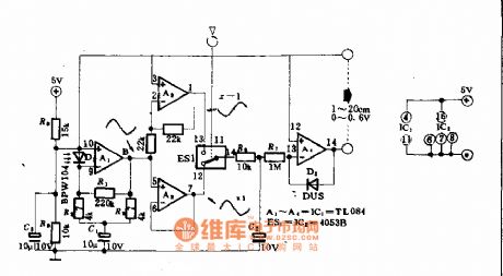
Lead-acid battery charger circuit diagram
Published:2014/3/4 19:55:00 Author:lynne | Keyword: Lead-acid battery charger circuit diagram,
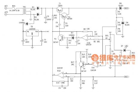
Because of the many advantages of sealed lead acid batteries , has received a wide range of applications . However, sealed lead-acid battery charging technology does not seem to be valued, because of the way unreasonable charging the battery prematurely scrapped caused widespread . In view of this , I designed a two-stage constant pressure limiting a lead-acid battery charger.Charging principles of analysis:1 maintenance charge :When the battery voltage is low ( can be set to a default in the circuit 9V or less ) , the charger work in small current maintenance charge state, the working principle is U1C ⑨ feet ( inverting terminal ) potential is lower than ⑧ feet ( inverting terminal ) , U1C output low , T4 deadline . U1D 11 feet potential of about 0.18V. At this point the charging current of about 250mA ( constant current circuit consists of R14, U1D, T1B surrounding peripheral circuits , constant self- analysis of the principle of the reader ) .2 Fast charging :With the continued maintenance charge , the battery voltage is gradually increased , when the battery voltage exceeds 9V, into high-current fast charge charger mode , U1C ⑨ feet ( inverting terminal ) potential higher than ⑧ feet ( inverting terminal ), U1C output high potential , T4 conduction , U1D 11 feet potential of about 0.48V, the charger output approximately constant 1A current to the battery .(3) limit pressure float :When the battery is nearly fully charged , the charger automatically transferred under pressure limiting floating state ( pressure limiting float voltage is set to 13.8V, such as 6V batteries, the float voltage should be set to 6.9V), this time charging current will gradually decrease from the fast charging, fully charged until the battery is fully charging current of only 10 ~ 30mA, to supplement the battery self-discharge and loss of power.4 circuit protection and charging indicator :The circuit has a reverse polarity protection circuit, the D4, U1C, U1D, T1 and peripheral components when reverse battery charger output current limiting without incident . Charging is indicated by U1A, D7 and peripheral components , charging , D7 lit, the battery charger into the floating state , D7 goes out , charging is finished.5 slightly modify the circuit parameters can be adjusted circuit charging current , float voltage battery with different specifications to meet the needs .Note : CF = carbon film resistors ; MF = Metal film resistors ; MOF = metal oxide film resistors* Can be adjusted according to said element .Lead-acid battery charger circuit diagram shown in Fig.:
(View)
View full Circuit Diagram | Comments | Reading(3640)
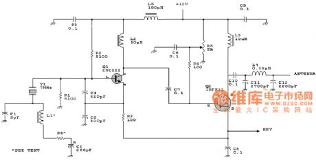
Ericsson phone charger circuit
Published:2014/3/3 20:34:00 Author:lynne | Keyword: Ericsson phone charger circuit,
Ericsson phone charger circuit shown in Figure:
(View)
View full Circuit Diagram | Comments | Reading(2840)
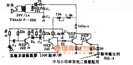
Strobe lights drive circuit diagram
Published:2014/3/3 20:13:00 Author: | Keyword: Strobe lights drive circuit diagram,
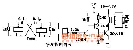
When the field control signal for low electricity at ordinary times, with the door closed, no signal output, this period is not bright neon lights.
1.5 K Ω for current-limiting resistance, protection, 3 dk4 value of B is good with 40-100, 3 dk4 B value in more than 40. Change 3 dk4 collector resistance, can change the current 3 dk4, to control the brightness of the light.
Magnetic core of pulse transformer with E12 at 11:45 type MXQ2000, primary 45 turns, wire diameter 0.51 mm enameled wire winding, the secondary use 0.21 mm high strength enamelled wire around 1500 turns. (View)
View full Circuit Diagram | Comments | Reading(1314)
Sound incentive switch circuit diagram
Published:2014/3/3 20:10:00 Author: | Keyword: Sound incentive switch circuit diagram,
Sound incentive switch circuit diagram
(View)
View full Circuit Diagram | Comments | Reading(1384)
Set method (multipath) driving display circuit diagram
Published:2014/3/3 20:05:00 Author: | Keyword: Set method (multipath) driving display circuit diagram,
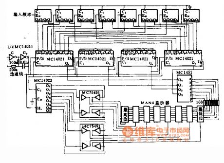
Set method (multipath) driving display circuit diagram
(View)
View full Circuit Diagram | Comments | Reading(1362)
Eight light-emitting diode drive circuit diagram
Published:2014/3/3 20:04:00 Author: | Keyword: Eight light-emitting diode drive circuit diagram,
Eight light-emitting diode drive circuit diagram
(View)
View full Circuit Diagram | Comments | Reading(1311)
Reverse polarity driving circuit diagram
Published:2014/3/3 19:58:00 Author: | Keyword: Reverse polarity driving circuit diagram,
Reverse polarity driving circuit diagram
(View)
View full Circuit Diagram | Comments | Reading(1345)
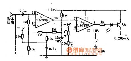
Visual CNC laser modulation drive circuit diagram
Published:2014/3/3 19:54:00 Author: | Keyword: Visual CNC laser modulation drive circuit diagram,
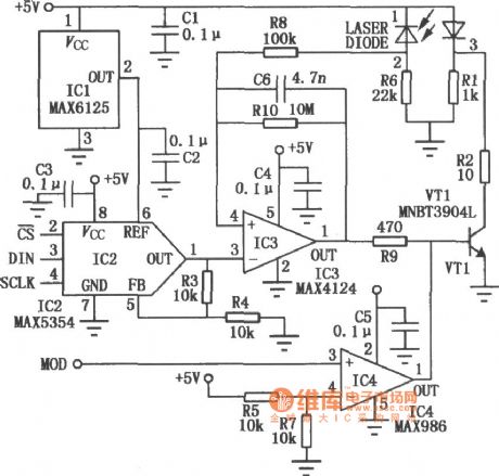
Visual CNC laser modulation drive circuit diagram
(View)
View full Circuit Diagram | Comments | Reading(1642)
400 hz light-emitting diode p combination of sine wave with operational amplifier circuit diagram
Published:2014/3/2 21:44:00 Author: | Keyword: 400 hz light-emitting diode p combination of sine wave with operational amplifier circuit diagram,
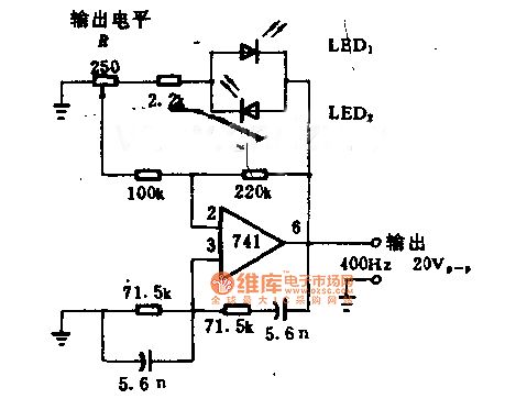
400 hz light-emitting diode p combination of sine wave with operational amplifier circuit diagram
(View)
View full Circuit Diagram | Comments | Reading(1457)
Photosensitive type oscillation circuit diagram
Published:2014/3/2 21:35:00 Author: | Keyword: Photosensitive type oscillation circuit diagram,
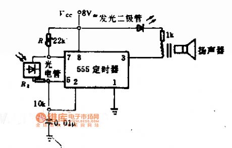
Photosensitive type oscillation circuit diagram
(View)
View full Circuit Diagram | Comments | Reading(1305)
Excelle electronic evaporative emission carbon can purge solenoid valve, camshaft position sensor, instrument cluster, and the speed sensor circuit diagram
Published:2014/3/2 21:32:00 Author: | Keyword: Excelle electronic evaporative emission carbon can purge solenoid valve, camshaft position sensor, instrument cluster, and the speed sensor circuit diagram,
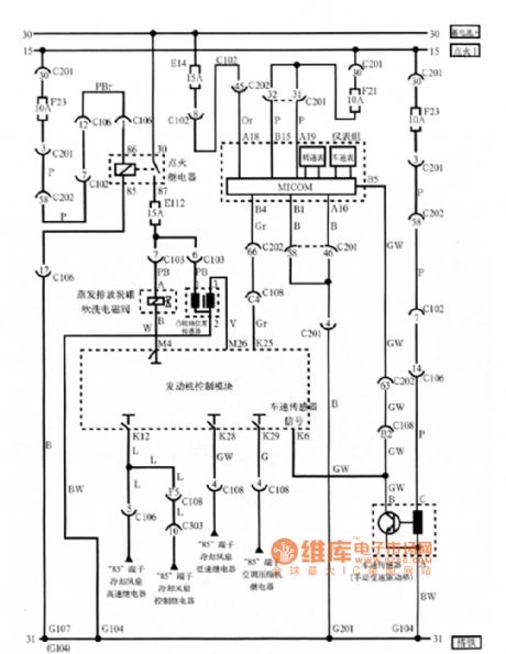
Excelle electronic evaporative emission carbon tank as shown purge solenoid valve, camshaft position sensor, instrument cluster, and the speed sensor circuit diagram (View)
View full Circuit Diagram | Comments | Reading(1403)
With double trigger a demo circuit diagram
Published:2014/3/2 21:31:00 Author: | Keyword: With double trigger a demo circuit diagram,
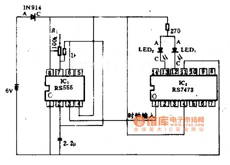
With double trigger a demo circuit diagram
(View)
View full Circuit Diagram | Comments | Reading(1341)
5 KHS photocell oscillation circuit diagram
Published:2014/3/2 21:29:00 Author: | Keyword: 5 KHS photocell oscillation circuit diagram,
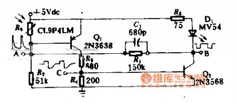
5 KHS photocell oscillation circuit diagram
(View)
View full Circuit Diagram | Comments | Reading(1338)
Solar power oscillation circuit diagram
Published:2014/3/2 21:28:00 Author: | Keyword: Solar power oscillation circuit diagram,
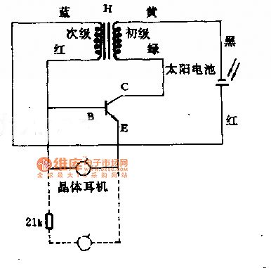

Solar power oscillation circuit diagram
(View)
View full Circuit Diagram | Comments | Reading(1516)
Light-emitting diodes (leds) with 1.25 w pulse generating circuit diagram
Published:2014/3/2 21:02:00 Author: | Keyword: Light-emitting diodes (leds) with 1.25 w pulse generating circuit diagram,
Light-emitting diodes (leds) with 1.25 w pulse generating circuit diagram (View)
View full Circuit Diagram | Comments | Reading(1036)
UC3842 power inverter circuit
Published:2014/2/27 21:05:00 Author:lynne | Keyword: UC3842 power inverter circuit,
UC3842 power inverter circuit shown in Figure:
(View)
View full Circuit Diagram | Comments | Reading(2642)
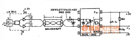
20 kbit cable receiving circuit diagram
Published:2014/2/27 20:17:00 Author: | Keyword: 20 kbit cable receiving circuit diagram,

20 kbit cable receiving circuit diagram
(View)
View full Circuit Diagram | Comments | Reading(1051)
Electro-optical distance receiver circuit diagram
Published:2014/2/27 20:11:00 Author: | Keyword: Electro-optical distance receiver circuit diagram,
Electro-optical distance receiver circuit diagram (View)
View full Circuit Diagram | Comments | Reading(1605)
| Pages:4/291 1234567891011121314151617181920Under 20 |
Circuit Categories
power supply circuit
Amplifier Circuit
Basic Circuit
LED and Light Circuit
Sensor Circuit
Signal Processing
Electrical Equipment Circuit
Control Circuit
Remote Control Circuit
A/D-D/A Converter Circuit
Audio Circuit
Measuring and Test Circuit
Communication Circuit
Computer-Related Circuit
555 Circuit
Automotive Circuit
Repairing Circuit