
Signal Processing
Index 27
Superregenerative radio receiver
Published:2012/11/23 0:50:00 Author:muriel | Keyword: Superregenerative, radio receiver
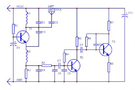
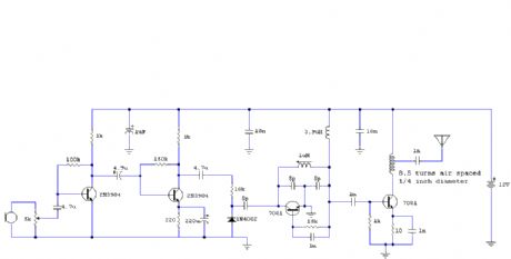
This is a simple RF receiver mainly for low-distance digital radio receiver application. The analog output of this circuit should be connected to a schmitt-trigger signal conditioning circuit with a proper value capacitor (from collector of T3). L1 for 27Mhz is about 10 turns, 6 mm diameter coil body. The circuit is suitable for other frequencies if L1 is changed. (View)
View full Circuit Diagram | Comments | Reading(2820)
Antenna Tuning Unit
Published:2012/11/23 0:48:00 Author:muriel | Keyword: Antenna Tuning Unit
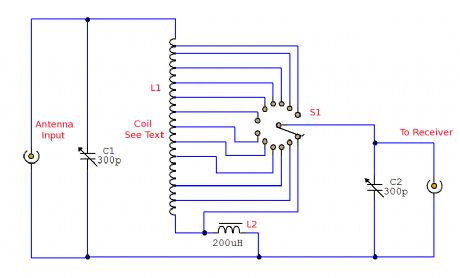
A simple passive (no power required) circuit to match an antenna to a radio receiver. This will be a useful addition to the short wave listener, but in addition a medium wave coil is almost used to tune the medium wave band. (View)
View full Circuit Diagram | Comments | Reading(1487)
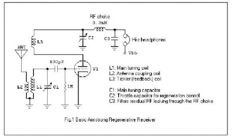
The Modern Armstrong Regenerative Receiver
Published:2012/11/23 0:47:00 Author:muriel | Keyword: Modern , Armstrong , Regenerative Receiver
View full Circuit Diagram | Comments | Reading(1867)
TV Transmitter circuits
Published:2012/11/23 0:46:00 Author:muriel | Keyword: TV Transmitter circuits
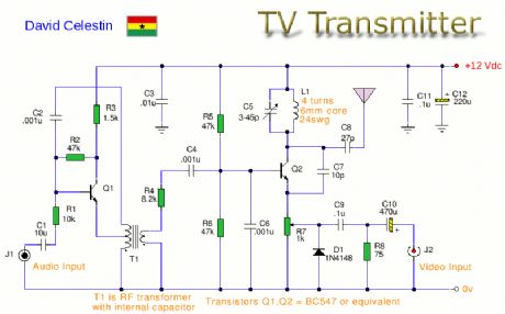
This is an Analogue TV Transmitter. Sound modulation is type FM with a 5.5MHz carrier and video transmission is PAL. Frequency is adjustable via C5 and tunes 54 to 216Mhz with components shown. This is suitable for countries using TV systems B and G. (View)
View full Circuit Diagram | Comments | Reading(2565)
FM Transmitter circuits
Published:2012/11/23 0:43:00 Author:muriel | Keyword: FM Transmitter circuits
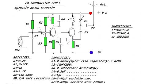
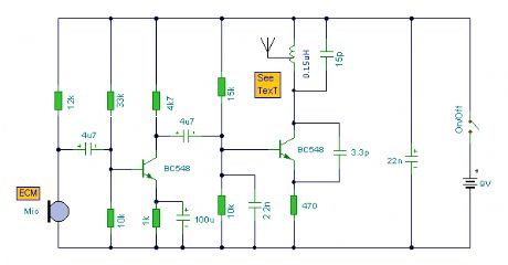
A portable FM transmitter that can be used to replace a FM microphone. (View)
View full Circuit Diagram | Comments | Reading(1054)
SW Regenerative Receiver
Published:2012/11/23 0:42:00 Author:muriel | Keyword: SW Regenerative, Receiver
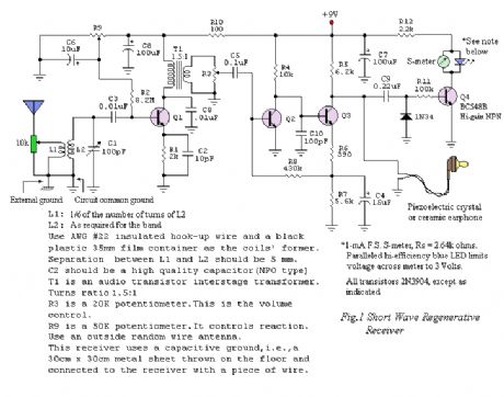
Sensitivity and selectivity are issues that will invariably concern a short wave listener when he wishes to purchase a new receiver. Commercially available communications equipment will undoubtedly fulfill his expectations, but we are talking here of highly priced products. Low-cost alternatives call mainly for homebrewed radios, and in this sense, the regenerative receiver is the common choice due to its simplicity, low parts count and very acceptable performance.
The author is also a short wave enthusiast and for some time used his family's Philips MW/SW vacuum tube radio. Later, he changed to a solid-state Sony ICF-7600, a high selectivity receiver featuring ceramic filters in the IF stages. Then he would discover how much fun he could have building radios on his spare time. After testing a variety of schematics available in books and on the web, the author finally decided to make his own designs.
Back in 2003, an experimental Colpitts-type shortwave regenerative receiver was made public on the web by this servant. It was reported to tune from the 22-meter band up to the 11-meter band with a single set of coils. Operation was found to be satisfactory with the prototype built on a protoboard and a ground plane fixed underneath. Further work with the receiver using different sets of coils revealed a larger usable frequency spectrum.
Fig.1 shows the schematic diagram of an improved version of the early receiver. It will tune signals from 3500kHz up to 26MHz, roughly in three bands, each with a 1.96:1 frequency-ratio. It must be quoted that the said frequency ratio is what the author got for his prototype. It is a function of the maximum-to-minimum capacitance of the variable tuning capacitor and the stray capacitance of the circuit layout. (View)
View full Circuit Diagram | Comments | Reading(3180)
A Bipolar Regenerative Receiver
Published:2012/11/23 0:40:00 Author:muriel | Keyword: Bipolar, Regenerative Receiver
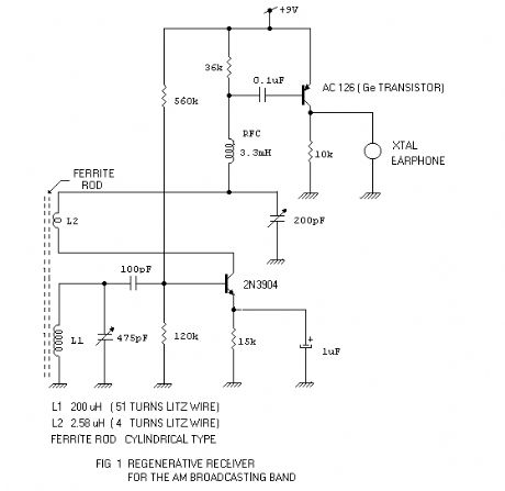
Contrary to what some radio experimenters think, a bipolar regenerative design can be made to work efficiently. The major concern is the low input impedance of the detector-amplifier bipolar stage. Nevertheless, it can be easily compensated with positive feedback or regeneration. A sufficient amount of regeneration can make tuning astonishingly sharp. Another concern is the quality of the detected audio. This, to my knowledge, is subjective. The quality of sound coming out from an earphone can be rated good or fair by two different people. I would suggest that you decide by yourself. So, come on and try the following schematic for the 530 kHz to 1650 kHz AM Broadcasting Band. (View)
View full Circuit Diagram | Comments | Reading(939)
FM Receiver
Published:2012/11/21 21:33:00 Author:muriel | Keyword: FM Receiver
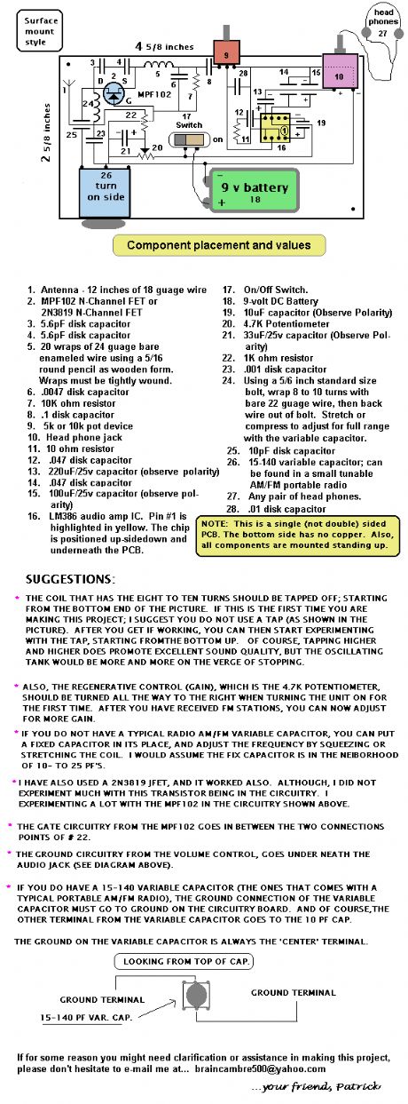
An FM regenerative receiver using a single FET and one audio amplifier IC. (View)
View full Circuit Diagram | Comments | Reading(701)
2 Transistor Transmitter
Published:2012/11/21 21:32:00 Author:muriel | Keyword: 2 Transistor, Transmitter

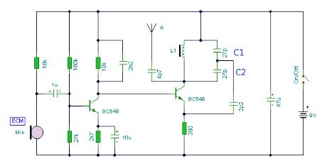
A compact 2 transistor transmitter for use at VHF frequencies. (View)
View full Circuit Diagram | Comments | Reading(786)
6 x 6 Loop Antenna
Published:2012/11/21 21:31:00 Author:muriel | Keyword: 6 x 6 , Loop Antenna
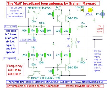
View full Circuit Diagram | Comments | Reading(837)
An AM voice transmitter
Published:2012/11/21 21:31:00 Author:muriel | Keyword: AM voice transmitter
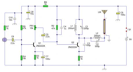
An AM voice transmitter with variable tuning. The antenna circuit is also tuned and transmits via a long wire antenna. Please Note. It is illegal to transmit on the AM wavebands in most countries, as such this circuit is shown for educational purposes only. (View)
View full Circuit Diagram | Comments | Reading(1522)
Zhenyu XSX - BIII electronic disinfecting cabinet ozone generator circuit
Published:2012/11/21 21:15:00 Author:Ecco | Keyword: Zhenyu , electronic disinfecting cabinet, ozone generator
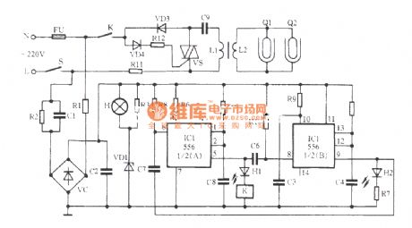
The ozone generator is the core circuit of the disinfection cabinet, while the core element is ozone glass tubes Q1 and Q2. And they form the ozone generating circuit with bidirectional thyristor VS and boost transformer T. When the AC power supply is in the negative half cycle, the diode VD3 gets conduction, VD4 is deadline, VS is turned off, then the power is charging for C9, and charging current flowing direction is AC power supply L side → R11 → L1 → C9 → N terminal. When the power supply is in the positive half cycle, VD3 is cut off, VD4 gets conduction, VS gets conduction, and the sufficient charge C9 makes instantaneous discharge through L1 → VS, then L1 generates larger transient discharge current induction in L2 and higher induced voltage.
(View)
View full Circuit Diagram | Comments | Reading(3159)
The ATL-3| Loop Antenna
Published:2012/11/21 21:29:00 Author:muriel | Keyword: ATL-3 Loop Antenna
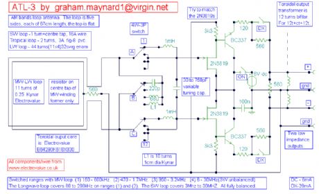
View full Circuit Diagram | Comments | Reading(796)
An low power FM Transmitter
Published:2012/11/21 21:27:00 Author:muriel | Keyword: low power , FM Transmitter

An low power FM Transmitter using an op-amp as the audio preamp and a single transistor as the RF amplifier. (View)
View full Circuit Diagram | Comments | Reading(1164)
4 Transistor Transmitter
Published:2012/11/21 21:24:00 Author:muriel | Keyword: 4 Transistor, Transmitter
View full Circuit Diagram | Comments | Reading(728)
A small FM voice transmitter for Band 2 VHF
Published:2012/11/21 21:22:00 Author:muriel | Keyword: FM voice transmitter, Band 2 VHF
View full Circuit Diagram | Comments | Reading(853)
2 Transistor FM Transmitter
Published:2012/11/21 21:16:00 Author:muriel | Keyword: 2 Transistor, FM Transmitter
View full Circuit Diagram | Comments | Reading(721)
SW Receiver Using ZN414
Published:2012/11/21 21:15:00 Author:muriel | Keyword: SW Receiver , ZN414
A Short Wave Receiver based on the MK484 (formerly ZN414) that includes the tropical bands and 49 metre bands. (View)
View full Circuit Diagram | Comments | Reading(1179)
ZN414 Portable Receiver
Published:2012/11/21 21:15:00 Author:muriel | Keyword: ZN414 , Portable Receiver
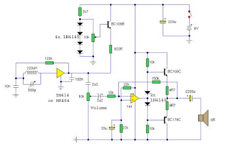
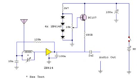
An AM portable radio receiver made from the ZN414 IC. The ZN414 ic has now been replaced by the MK484 which is identical in performance and pinout. (View)
View full Circuit Diagram | Comments | Reading(1045)
4 Band Double Tuned Preselector
Published:2012/11/21 21:14:00 Author:muriel | Keyword: 4 Band , Double, Tuned Preselector
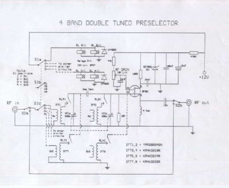
The circuit requires an RF input which can be from a longwire or a loop antenna. The Preamplifier has a range from 550kHz (Medium Wave) up to 30 MHz in the SW band. The input Switch S1, applies voltage to a set of relays which switch in the appropriate coils.The preamplifier is double tuned on the input having two IFT coils for each RF range, input applied to G1 of a double gate MOSFET. Gain control is applied to G2 and the output is taken from the DGMOSFET drain terminal. Click here for a picture of a MW loop. Click hereto view a finished picture of this project. (View)
View full Circuit Diagram | Comments | Reading(1176)
| Pages:27/195 At 202122232425262728293031323334353637383940Under 20 |
Circuit Categories
power supply circuit
Amplifier Circuit
Basic Circuit
LED and Light Circuit
Sensor Circuit
Signal Processing
Electrical Equipment Circuit
Control Circuit
Remote Control Circuit
A/D-D/A Converter Circuit
Audio Circuit
Measuring and Test Circuit
Communication Circuit
Computer-Related Circuit
555 Circuit
Automotive Circuit
Repairing Circuit