
Signal Processing
Index 28
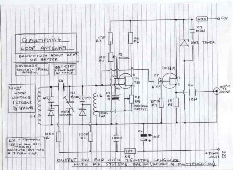
Q- Multiplying Loop Antenna
Published:2012/11/21 21:13:00 Author:muriel | Keyword: Q- Multiplying, Loop Antenna
View full Circuit Diagram | Comments | Reading(998)
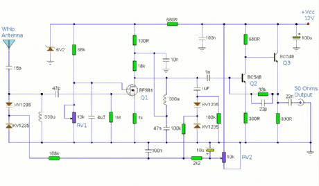
Medium Wave Active Antenna
Published:2012/11/21 21:13:00 Author:muriel | Keyword: Medium Wave , Active Antenna
View full Circuit Diagram | Comments | Reading(1262)
AM Receiver
Published:2012/11/21 21:12:00 Author:muriel | Keyword: AM Receiver
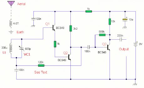
This is a compact three transistor, TRF receiver with fixed feedback. It is similar in principle to the ZN414 which is now replaced by the MK484. The design is simple and sensitivity and selectivity of the receiver are good. (View)
View full Circuit Diagram | Comments | Reading(1074)
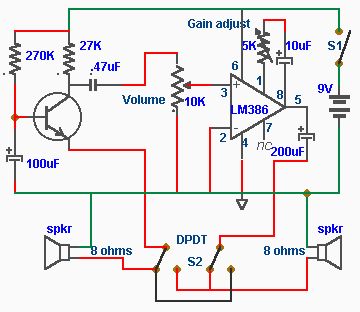
Doorphone Intercom circuit
Published:2012/11/19 21:49:00 Author:muriel | Keyword: Doorphone Intercom circuit

A simple Intercom made with a single transistor and low power audio amplifier LM386. The circui uses 8 ohm speakers, which also double as a microphone.
(View)
View full Circuit Diagram | Comments | Reading(1755)
Doorphone Intercom
Published:2012/11/19 21:39:00 Author:muriel | Keyword: Doorphone Intercom
A simple Intercom made with a single transistor and low power audio amplifier LM386. The circui uses 8 ohm speakers, which also double as a microphone. (View)
View full Circuit Diagram | Comments | Reading(803)
6 Input Mixer
Published:2012/11/19 21:36:00 Author:muriel | Keyword: 6 Input , Mixer
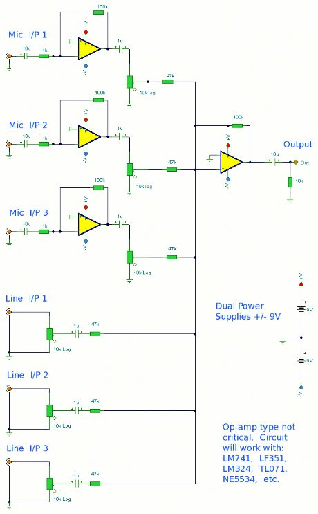
A simple mixer with 3 line inputs and 3 mic inputs using commonly available parts. (View)
View full Circuit Diagram | Comments | Reading(948)
Notch Filter
Published:2012/11/19 21:35:00 Author:muriel | Keyword: Notch Filter
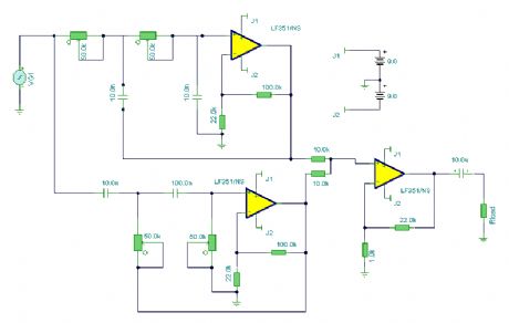
A variable notch filter with both high and low pass filters. (View)
View full Circuit Diagram | Comments | Reading(1099)
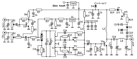
Wireless Microphone FM Transmitter
Published:2012/11/15 21:16:00 Author:muriel | Keyword: Wireless, Microphone , FM , Transmitter
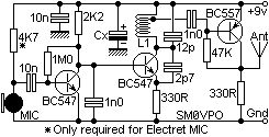
This Wireless Microphone FM Transmitter has been a very popular project with beginners and experienced constructors alike. It has been used inside guitars and as the basis of a remote control system. I do however, receive many requests for a higher powered circuit and better microphone sensitivity. Now I can introduce the new FM Wireless Microphone, which also has a better frequency stability, over 1Km range (under ideal conditions) and is good on microphone sensitivity. This has been achieved by adding an RF amplifier buffer (with 10dB gain) and an AF preamplifier to boost the modulation a little.
Construction is quite simple. L1 is 3.25 turns in spiral form and is an integral part of the PCB foil pattern. The two BC547 transistors can be replaced with (almost) any small-signal NPN transistor, such as the 2N2222. The final stage is a BC557 PNP general purpose device. If you use different devices then you should select the 1M0 resistor for 5-volts DC at the collector of the the first transistor. Select the 47K resistor for 3 - 4 volts on the collector of the third transistor. Here is the V5 component overlay drawing. Note that there is a modification: There used to be a 1n0 5mm cap for supply decoupling, but after a cange of component supplier (manufacturer?) there developed some form of RF instability when the gain of the PA transistor was a little above normal. Replacing the 1n0 to an electrolytic capacitor of 22uf cured this problem totally. Any radial (the leads both come out of the same end) type electrolytic capacitor from 0.47uf upwards cures the problem. The finished unit draws about 30mA which should vary as you touch the tuned circuit, a good test that the unit is oscillating. You should remove the 4K7 resistor if you use a dynamic microphone. The PCB is 50mm x 25mm, a little larger than the first version but there are three stages instead of just the one. The first prototype is shown above, beside the battery powering it. The output power is about +10dBm which is about 10dB more than the first FM Wireless Microphone. This would theoretically give it 3.12 times the range (1.6Km) but I have only tested it using a handheld receiver with the TX laying on the bench indoors. But I got a comfortable 700 meters (and a few funny looks from our neighbours). Above you can see the addition of a gimmick capacitor added across the 12p tuning capacitor to lower the frequency of the transmitter. Make the capacitor by twisting two lengths of single core insulated hook-up wire, about 2cm long. This will reduce the frequency to the bottom end of the band. Cut short the capacitor to increase the frequency to the desired final frequency. If you cut it a few KHz too high then just twist the gimmick a little tighter. The PCB foil pattern and layout will be placed in the download section of my homepages. Have fun and please be aware that the higher power of this project may render it ILLEGAL in your own country. I can accept no responsibility and it is up to you to check that you may legally use it. I will accept NO complaints from any country/state correctional facility.
(View)
View full Circuit Diagram | Comments | Reading(1459)
Video/Audio Wireless Transmitter
Published:2012/11/15 21:13:00 Author:muriel | Keyword: Video/Audio , Wireless , Transmitter
Television signals operates as two separate transmissions. One for the video and the other for sound. And just like our project, two different devices are going to be built. (View)
View full Circuit Diagram | Comments | Reading(1808)
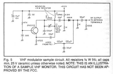
VHF/UHF TV Modulator2
Published:2012/11/15 21:12:00 Author:muriel | Keyword: VHF/UHF , TV, Modulator
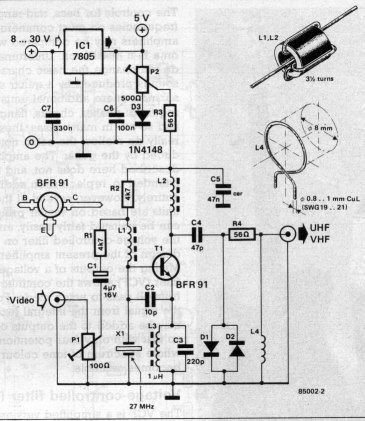
Simple oscillator that generates a frequency in the VHF or UHF region. The oscillator is modulated with the video signal and the modulated carrier wave thus generated is fed into the TV set's aerial input via a cable. Then all that remains to do is tune the TV to the correct frequency. (View)
View full Circuit Diagram | Comments | Reading(1337)
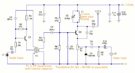
VHF Video Transmitter 60-200 MHz
Published:2012/11/15 21:09:00 Author:muriel | Keyword: VHF, Video, Transmitter, 60-200 MHz
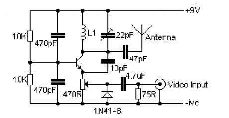
Here's a simple video transmitter for VHF TV channel will accept baseband video input, hence it can be driven by most CCD cameras and VCR video outputs. It ouputs roughly 80mW and when used with a 40cm telescopic antenna over 100 meters range is possible.
The transistor of the video transmitter can be a BC108, BC546, BC337 or a 2N2222. L1 is wound on a 10 mm air former. Use 6 turns 24 SWG for frequency 60-80 MHz, 4 turns for 150-180 MHz, and 2 turns for 180-200 MHz You can use this with a monochrome or color video signal. To transmit sound just build the wide band FM transmitter and tune it to the audio channel.
(View)
View full Circuit Diagram | Comments | Reading(2993)
VHF FM Transmitter MAX2606
Published:2012/11/15 21:08:00 Author:muriel | Keyword: VHF, FM, Transmitter, MAX2606
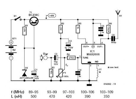
If you want to be independent of the local radio stations for testing VHF receivers, you need a frequency-modulated oscillator that covers the range of 89.5 to 108 MHz � but building such an oscillator using discrete components is not that easy. Maxim now has available a series of five integrated oscillator building blocks in the MAX260x series which cover the frequency range between 45 and 650 MHz. The only other thing you need is a suitable external coil, dimensioned for the midrange frequency.
The MAX2606 covers the VHF band, although the frequency can only be varied by approximately �3 MHz around the midrange frequency set by the coil L. The inductance values shown in the table can serve as starting points for further experimenting. The SMD coils of the Stettner 5503 series are suitable for such oscillators. In Germany, they are available from B黵klin (www.buerklin.de), with values between 12 nH and 1200 nH. You can thus directly put together any desired value using two suitable coils. If you want to wind your own coils, try using 8 to 14 turns of 0.5-mm diameter silver-plated copper wire on a 5-mm mandrel. You can make fine adjustments to the inductance of the coil by slightly spreading or compressing the coil. The circuit draws power from a 9-V battery. The BC238C stabilises the voltage to approximately 4 V. Although the MAX2606 can work with a supply voltage between +2.7 V and +5.5 V, a stabilised voltage improves the frequency stability of the free-running oscillator. The supply voltage connection Vcc (pin 5) and the TUNE voltage (pin 3) must be decoupled by 1-nF capacitors located as close as possible to the IC pins. The tuning voltage TUNE on pin 3 may lie between +0.4 V and +2.4 V. A symmetric output is provided by the OUT+ and OUT� pins. In the simplest case, the output can be used in a single-ended configuration. Pull-up resistors are connected to each of the outputs for this purpose. You can use a capacitor to tap off the radio signal from either one of these resistors. Several milliwatts of power are available. At the audio input, a signal amplitude of 10 to 20 mV is enough to generate the standard VHF frequency deviation of �40 kHz. (View)
View full Circuit Diagram | Comments | Reading(2326)
VHF Audio Video Transmitter2
Published:2012/11/15 21:01:00 Author:muriel | Keyword: VHF, Audio, Video, Transmitter

View full Circuit Diagram | Comments | Reading(1011)
VHF Audio Video Transmitter
Published:2012/11/15 21:01:00 Author:muriel | Keyword: VHF, Audio, Video, Transmitter
View full Circuit Diagram | Comments | Reading(2515)
VERONICA 1W - 5W FM Transmitter
Published:2012/11/15 21:00:00 Author:muriel | Keyword: VERONICA , 1W - 5W , FM , Transmitter
The Veronica is an easy to build and tune transmitter for the FM band. It's known for it's stability and clean signal, does not use any IC's or similar specialized parts, and it has a built-in tuning aid that makes it possible to tune it with no extra equipment. It's available in two versions, 1 and 5 watts.
(View)
View full Circuit Diagram | Comments | Reading(1893)
USB Mono FM Transmitter
Published:2012/11/15 20:57:00 Author:muriel | Keyword: USB, Mono, FM, Transmitter
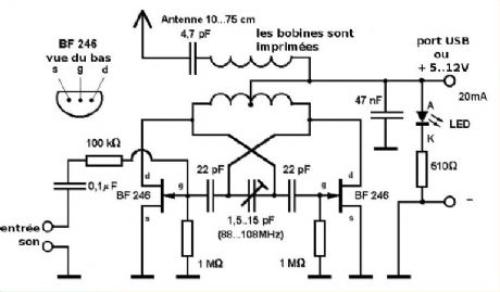
This small FM transmitter with a range of about 50 meters designed for connection to the USB port. With lots of mini-transmitters then you have a comprehensive, action-packed radio program. Due to the power supply via the USB port of a high frequency stability is achieved. Alternatively, the receiver, a battery 5 to 12 volts to operate.
FM Transmitter Construction USB FM Transmitter Prototype It is not necessary to drill the transmitter PCB. All components will be soldered to the plate with their legs folded, like this: The two transistors and the LEDs are polarized: The transistor has a flat side, the LED a foot longer than the other is the anode (A), the other is the cathode (K). The audio cable (minijack) must be transformed from a stereo cable into a cable. Mono Sound: Soldering together the white and red cables, leaving aside the yellow cable (mass). The frequency setting will be turning the variable capacitor gently with a screwdriver or thin cardboard but rigid. FM Transmitter Parts List 1 Ohm resistor 510 (green � brown � brown) 100 resistor 1 kOhm (brown � black � yellow) 1 MOhm resistors (brown � black � green) 1 capacitor 0.1 uF (0.1) 1 nF capacitor 47 (0.047) 1 capacitor 4.7 pF (479) 2 pF capacitors 22 (22) 1 variable capacitor 1.5 pF � 15 2 transistor BF 246 (F246A) 1 red LED 1 audio cable (minijack) (View)
View full Circuit Diagram | Comments | Reading(3117)
USB FM Transmitter MAX2606
Published:2012/11/15 20:56:00 Author:muriel | Keyword: USB , FM , Transmitter , MAX2606
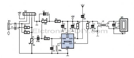
This MP3 Player FM transmitter can be used to listen to your own music throughout your home. The transmitter circuit use no coils that have to be wound. When this FM transmitter used in the car, there is no need for a separate input to the car stereo to play back the music files from your MP3 player. (View)
View full Circuit Diagram | Comments | Reading(1802)
USB FM Transmitter
Published:2012/11/15 20:55:00 Author:muriel | Keyword: USB , FM, Transmitter
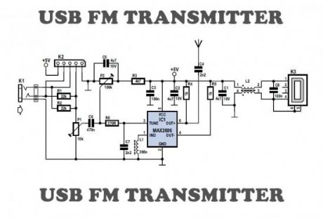
Here is a simple USB FM transmitter that could be used to play audio files from an MP3 player or computer on a standard VHF FM radio by connecting it to an USB port. The circuit use no coils that have to be wound. This USB transmitter can be used to listen to your own music throughout your home. To keep the fm transmitter circuit simple as well as compact, it was decided to use a chip made by Maxim Integrated Products, the MAX2606. This IC from the MAX2605-MAX2609 series has been specifically designed for low-noise RF applications with a fixed frequency. The VCO (Voltage Controlled Oscillator) in this IC uses a Colpitts oscillator circuit. The variable-capacitance (varicap) diode and feedback capacitors for the tuning have also been integrated on this chip, so that you only need an external inductor to fix the central oscillator frequency. (View)
View full Circuit Diagram | Comments | Reading(1605)
TV Video Transmitter
Published:2012/11/15 20:51:00 Author:muriel | Keyword: TV , Video, Transmitter
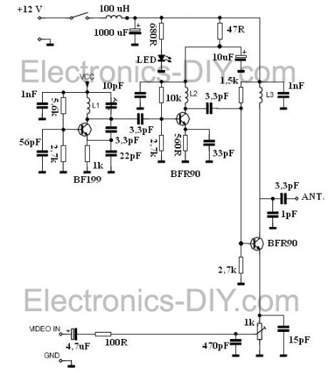
This is a TV transmitter for transmitting video of various video sources such as video cameras, Satellite receivers, DVD players, game consoles, etc. TV transmitter's circuit is working on the 470-580 MHz frequency and can be received on UHF channels 21-34. TV Video transmitter can radiate as far as 300 meters by using a 10-20 cm wire antenna. TV transmitter requires voltage of 9-15 Volts. However, you can also use a 9v batteries. Oscillator is based around BF199 and BFR90 RF transistors. If needed the range of TV transmitter can be extended by replacing BFR90 with 2N3886 transistors. (View)
View full Circuit Diagram | Comments | Reading(2424)
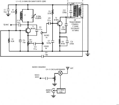
TV Transmitter Circuit2
Published:2012/11/15 20:50:00 Author:muriel | Keyword: TV, Transmitter Circuit
This is a small TV transmitter circuit which transmits in VHF band, negative sound modulation and PAL video modulation. It is suitable in countries where the B and G system is used. (View)
View full Circuit Diagram | Comments | Reading(1209)
| Pages:28/195 At 202122232425262728293031323334353637383940Under 20 |
Circuit Categories
power supply circuit
Amplifier Circuit
Basic Circuit
LED and Light Circuit
Sensor Circuit
Signal Processing
Electrical Equipment Circuit
Control Circuit
Remote Control Circuit
A/D-D/A Converter Circuit
Audio Circuit
Measuring and Test Circuit
Communication Circuit
Computer-Related Circuit
555 Circuit
Automotive Circuit
Repairing Circuit