
Signal Processing
Index 31
Coilless FM Transmitter
Published:2012/11/14 0:50:00 Author:muriel | Keyword: Coilless , FM, Transmitter
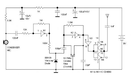
The RF oscillator using the inverter N2 and 10.7Mhz ceramic filter is driving the parallel combination of N4 to N6 through N3.Since these inverters are in parallel the output impedance will be low so that it can directly drive an aerial of 1/4th wavelength. Since the output of N4-N6 is square wave there will be a lot of harmonics in it. The 9th harmonics of 10.7Mhz (96.3Mhz) will hence be at the center of the FM band. N1 is working as an audio amplifier. The audio signals from the microphone are amplified and fed to the varicap diode. The signal varies the capacitance of the varicap and hence varies the oscillator frequency which produce Frequency Modulation. (View)
View full Circuit Diagram | Comments | Reading(2498)
CB Transmitter
Published:2012/11/14 0:49:00 Author:muriel | Keyword: CB Transmitter
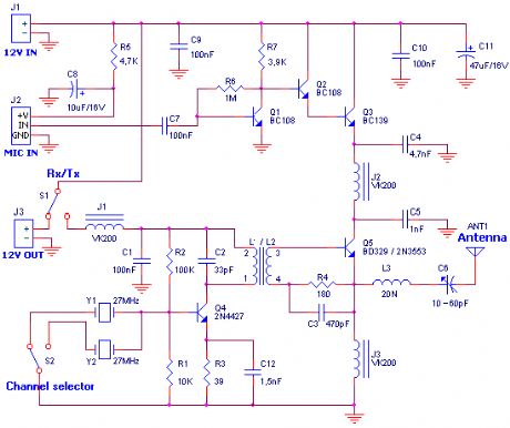
For the regulation it needs a voltmeter (with needle better) and charge 50W/5W. Connect charge 50W in the place of aerial, with the voltmeter in the exit voltmeter. Be supplied the transmitter with + 12V. It will be supposed we have consumption between 0,7-1A. With a screwdriver we regulate the core of inductor L1/L2 and later the variable C6 until we see the biggest tendency. We connect the microphone and speaking we observe the clue in the multimeter. If all have become right will be supposed the tendency, speaking, to go up roughly 30-35%. (View)
View full Circuit Diagram | Comments | Reading(1038)
Camera VHF Video Transmitter
Published:2012/11/14 0:48:00 Author:muriel | Keyword: Camera , VHF Video, Transmitter
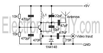
This is a simple video transmitter that can transmit as far as 50 meters. This video transmitter can be used with the camera or other video sources. You can view them on VHF channel analog TV. Supply voltage to the video transmitter can use 9V battery. Transistor components that are used for a video transmitter is BC548 or you can use another type of transistor BF199. Meanwhile, other passive components used SMD type. For winding coil L1 is 5 Turns 8 mm in diameter and use wire AWG 0.3-0.5 mm.
Once you up the circuit this video transmitter, antenna use as a cable along the 50 cm. To determine the frequency of work, turn the trimmer capacitor 22 pf accordance with the frequency that you want.
(View)
View full Circuit Diagram | Comments | Reading(3745)
Building Simple FM Transmitter
Published:2012/11/14 0:47:00 Author:muriel | Keyword: Simple , FM Transmitter
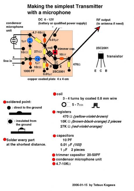
Here's how to build a simple FM Transmitter. This tiny transmitter has smaller radius of the service area, lower quality of the sounds and the relatively unstable frequency. These can be considered as a compromise to easily have your own transmitter for the time being or as a more positive choice. These defects are only from the perspective of conventional transmission such as clear stereo sound to receive anywhere . Artist could change these to another directions. Whether or not, you can experience a convivial wireless imagination by this transmitter. (View)
View full Circuit Diagram | Comments | Reading(982)
Broadcast FM Transmitter
Published:2012/11/14 0:45:00 Author:muriel | Keyword: Broadcast , FM Transmitter
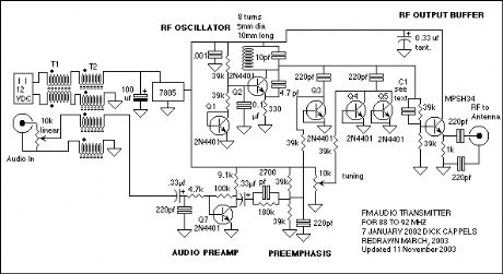
Here's a nice AC mains powered FM Broadcast Audio Transmitter with pre-emphasis, audio level control, and tuning control. The circuit consists of a frequency modulated oscillator, an audio preamplifier with pre emphasis to supply the frequency modulating signal, and a buffer amplifier to drive the antenna connector. Oscillator's frequency is determined by L1 resonating with the 10 pf capacitor and the total capacitance across it. The collector-base capacitance of the transistors Q3, Q4, and Q5 is a function of their revers bias. This is basically a poor man's (or lazy man's) varactor. The voltage across Q3 is set by a voltage divider and is then modulated by an Ac coupled audio signal from the pre amp, causing the reverse bias to vary with the audio signal, which changes the resonant frequency of L1's circuit, causing the frequency of the oscillator to vary with the audio signal. The capacitance of Q4 and Q5 is adjusted by DC bias from the tuning adjustment potentiometer, and this capacitance sets the center frequency of the oscillator. All of the transistors in the oscillator -Q1 through Q5, are 2N4401. The purpose of the buffer is to minimize frequency shift as loading on the antenna is changed. It was specifically designed to reduce the signal amplitude to the antenna. Transmitters should not use any more power than is necessary to achieve the task at hand, and lightly coupling the RF into the buffer's base with a gimmick capacitor did the trick. The transistor is an MPSH34. (View)
View full Circuit Diagram | Comments | Reading(1797)
BH1417 USB FM Transmitter
Published:2012/11/14 0:44:00 Author:muriel | Keyword: BH1417 , USB , FM Transmitter
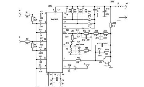
Here's BH1417 USB FM Transmitter with built-in PLL circuit. Its low-frequency signal is converted into high-frequency, which can take any audio device with FM radio (stereo, car CD, MP3, DVD player, etc.), as a normal radio station. Transmitter power is sufficient for reliable reception of its signal within a few tens of meters. The basis of the device is a chip BH1417F, included in a typical scheme. This device contains all the necessary circuitry to generate a composite stereo signal c of the pilot tone, the RF generator with PLL and power amplifier. A detailed description is given in. (View)
View full Circuit Diagram | Comments | Reading(2342)
BH1415F FM Stereo PLL Transmitter
Published:2012/11/14 0:42:00 Author:muriel | Keyword: BH1415F, FM , Stereo, PLL Transmitter
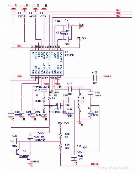
Transmitter power amplifier, the output signal from BH1415F by 2 SC9018, 2SC3355, 2SC2053 amplified signal can reach more than 500 mW, adjusting well to achieve greater power. Measured by the pull rod antenna used to be launched in the open 800 meters above. Uses external antenna will be launched even further. attention in 2053 need to be installed and tested at the load connected to leave, or else very easily burn 2053, 50 European amateur production of 2 W can be used instead of resistance. installed and tested at three levels circuit can be installed and tested. (View)
View full Circuit Diagram | Comments | Reading(2617)
BandPass Filter circuits
Published:2012/11/14 0:41:00 Author:muriel | Keyword: BandPass Filter circuits
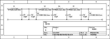
This bandpass filter is in fact a combined high- and lowpassfilter. The first stages are a highpass (f>70MHz) and the last stages a low pass (f<180MHz). The lost of this filter is several watts when driven with 20[Watts], but the output signal is (when adjusted with a spectrum analyser) very clean. (View)
View full Circuit Diagram | Comments | Reading(1194)
BA1404 Transmitter with UPC1651RF Amplifier
Published:2012/11/14 0:38:00 Author:muriel | Keyword: BA1404, Transmitter , UPC1651RF, Amplifier
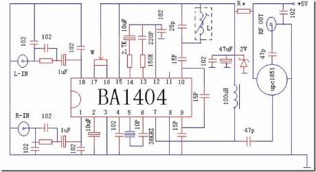
BA1404 transmitter includes onboard RF amplifier for increased transmitting range. Operating voltage range is 1-3V, the circuit contains FM stereo mixer, 38KHZ oscillator, FM modulator and high-frequency amplifier monolithic integrated circuit. As the electronic newspaper BBS there are many users requiring detailed information on the FM stereo transmitter, so I re-collect the relevant information on the simple discrete, merge, integrated FM stereo transmitter experiment, that BA1404 with μpc1651 mix of the most easy to make and debug, and very high frequency stability (relative to the previous circuit BA1404), transmission power is increased by UPC1651RF amplifier. (View)
View full Circuit Diagram | Comments | Reading(1475)
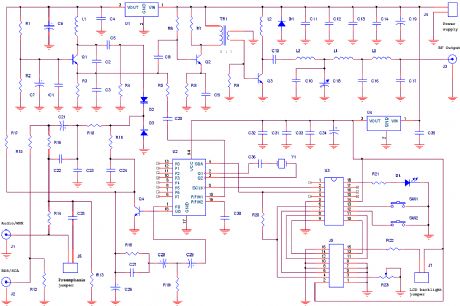
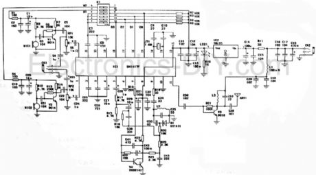
8W PLL Stereo Transmitter with LCD
Published:2012/11/14 0:36:00 Author:muriel | Keyword: 8W , PLL , Stereo Transmitter , LCD
Very stable PLL FM transmitter based on TSA5511 synthesizer. Frequency is performed with three buttons through PIC16F84 microcontroller. Frequency is displayed on 16x1 LCD. Transmitter oscillator is based around BF981, BFR91, BFR96 transistors. 2SC1971 RF power transistor can be replaced with 2N4427 or 2N3553 but they will provide less output power. (View)
View full Circuit Diagram | Comments | Reading(2997)
80 MHz - 108 MHz FM Transmitter
Published:2012/11/14 0:30:00 Author:muriel | Keyword: 80 MHz - 108 MHz, FM, Transmitter

FM transmitter or often called fm transmitter uses 2 transistors in this article uses 2 transistors 2n2222. If the fm transmitter is in use voltage supply of 9 volt battery and use an antenna whose length is less than 12 inches, then this fm transmitter will be within FCC limits. Signals from the microphone in the fm transmitter is reinforced by Q1, Q2 with carrier frequency generator is determined by the C5 and L1. The frequency of the FM transmitter is in the range 80 MHz - 108 MHz. L1 can be made with as many as 24 e-mail wire wrap and 6 wrap. The following is a picture series for the fm transmitter fm transmitter referred to in article 2 of this transistor.
This fm transmitter antenna is connected to the mid point of the antenna length L1 and preferably between 8-12 inches. FM Transmitter is only used for experiment and learning materials are not to be used for day-to-day, because the use of FM transmitter frequency regulated and protected by law may be understandable.
(View)
View full Circuit Diagram | Comments | Reading(1025)
75 Meter SSB Transceiver
Published:2012/11/14 0:27:00 Author:muriel | Keyword: 75 Meter , SSB, Transceiver
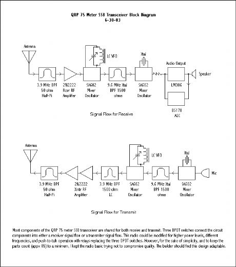
Here's 75 Meter QRP SSB Transceiver. In general, the transceiver switches the 4-element 1500 ohm xtal BPF ends between the inputs and outputs of the two SA602s to reverse the signal flow for R/T operation. Since no IF amplifier is used in the design, 20 dB of additional receiver gain is produced by the 2N2222 receiver RF amplifier, while automatic gain control (AGC) is produced by the peak DC swing of the LM386 output passed through a rectifier and filtered by a capacitor and fed to the gate of a BS170 enhancement mode FET acting as a variable resistor across the input of the LM386. Both receive and transmit band pass filtering are done by the same half-pi BPF. The diode pair in the mic circuit reduce the chirp that occurs during the R/T transition. Additional BS170s could easily be used to mute both the mic and audio instead of the R/T switch directly. These BS170s would be controlled by the +R and +T voltages on their gates while their drains would be tied to 1) the mic circuit between the two coupling capacitors and 2) pin number 1 (audio in) of the LM386 (BS170 sources to ground). Additional power output (perhaps 60 mW) could also be attained by connecting the RF output transistor's collector choke (10 uH) to a 9 V supply instead of the 5 V. Additional biasing current might also be required for this change. (View)
View full Circuit Diagram | Comments | Reading(1081)
5W PLL FM Transmitter
Published:2012/11/13 21:59:00 Author:muriel | Keyword: 5W , PLL , FM, Transmitter
Easy to build high-quality PLL FM transmitter with typical output power of 5 W and no-tune design. The transmitter includes RDS/SCA input and Audio/MPX input with optional pre-emphasis. It can be used with or without stereo encoder. Tuning over the FM band is provided by two buttons that control dual-speed PLL. The transmitter can work also without the LCD display. Some experience with building devices of this kind are highly recommended. (View)
View full Circuit Diagram | Comments | Reading(2041)
50mW BH1417 Stereo PLL FM Transmitter
Published:2012/11/13 21:58:00 Author:muriel | Keyword: 50mW, BH1417 , Stereo, PLL , FM Transmitter
This is an excellent 50mW Hi-Fi PLL FM Stereo Transmitter that features BH1417 chip. ROHM's new Japan has BH1417 is one of the most simple and practical integrated circuits, which combines phase-locked loop circuit, stereo encoder circuit, transmitter circuit, as well as other additions. Pre-emphasis circuit, limiter circuit and low pass filter can significantly improve the sound quality. The total harmonic distortion up 0.3%, stereo separation to 40dB, RF output level is 100dB. BH1417F is an excellent new IC chip, this circuit improves signal to noise ratio (S / N) of pre-emphasis circuit to prevent signal over emphasized limiting circuit, the control input signal frequency low-pass filter circuit (LPF), generate stereo stereo composite signal modulation circuit, FM transmitter phase-locked loop circuit (PLL) component. BH1417F excellent frequency characteristics, it can achieve 40dB of isolation, transmitted sound quality is similar to local FM radio stations. (View)
View full Circuit Diagram | Comments | Reading(3016)
500mW PLL FM Transmitter 88-108MHz
Published:2012/11/13 21:57:00 Author:muriel | Keyword: 500mW, PLL, FM , Transmitter , 88-108MHz
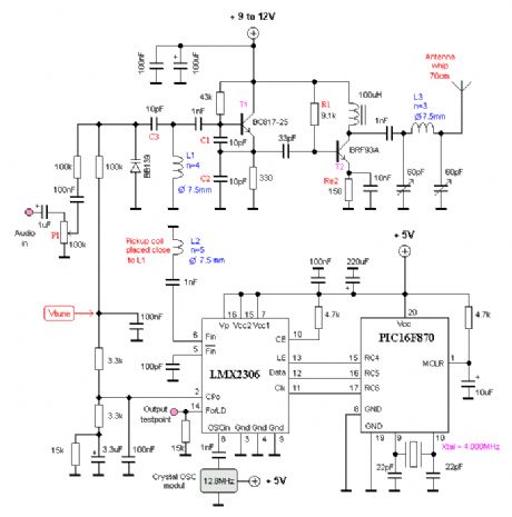
This PLL transmitter is controlled and the frequency is very stable and can be programmed digitally. Transmitter will work 88-108 MHz and output power up to 500mW. With a small change can set the frequency of 50-150 MHz. The output power is often set to several watts with transistors. So therefore I decided to build a simple transmitter with great performances. The frequency of this transmitter can easily be changed by software and space / compress air coil. This transmitter is the oscillator colpitts. Oscillator is a VCO (voltage controlled oscillator) which is set by the PLL circuit and PIC micro controller. This oscillator is called the Colpitts oscillator and voltage controlled to achieve the FM (frequency modulation) and PLL control. (View)
View full Circuit Diagram | Comments | Reading(1759)
5 Watt Transmitter
Published:2012/11/13 21:47:00 Author:muriel | Keyword: 5 Watt , Transmitter
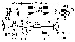
This is a very simple 5 watt CW TX based upon a TTL logic chip. There is just one tricky component and this is Cx. This component should have an impedance of about 10 - 50 ohms at the frequency of interest. If you wish to reduce the transmitter power, increase the value of Cx. It is Cx which causes the square wave from the output transistor to approximate a sine waveform. The value of Cx is the price of simplicity in this TX. (View)
View full Circuit Diagram | Comments | Reading(1484)
The PLL synthesized oscillator circuit diagram
Published:2012/11/11 20:16:00 Author:Ecco | Keyword: PLL , synthesized oscillator
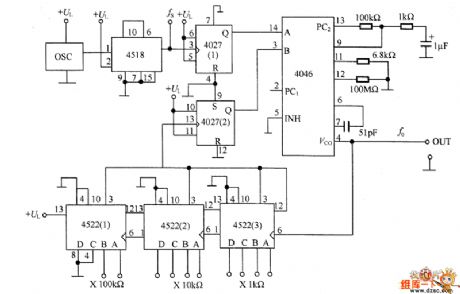
PLL synthesizer oscillator circuit is a feedback loop composed of reference oscillator, phase comparator, loop filter, voltage controlled oscillator, programmable frequency divider and other components. In the circuit, the reference oscillator uses a crystal oscillator (OSC) to output 1MHz or l00kHz 1/1000 or 1/100 divider and generate 1kHz signal, then it is compared with the output of 1 / N sub- frequency circuit. 4046 contains PC1 and PC2 two-phase comparators which can obtain the output corresponding to phase difference or frequency.
(View)
View full Circuit Diagram | Comments | Reading(5797)
The oscillator circuit diagram composed of crystal inverter
Published:2012/11/11 21:19:00 Author:Ecco | Keyword: oscillator , crystal inverter
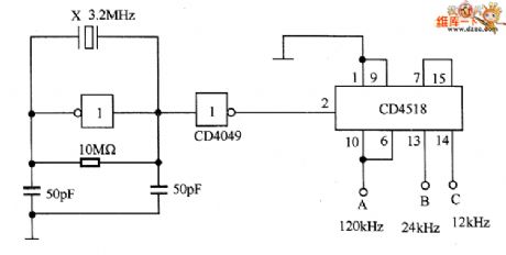
In the circuit, crystal X ( 3.2MHz ) forms the oscillator circuit, after its oscillation output is connected to BCD counter CD4518, it will divide the original oscillation frequency, then the CD4518's different output ends can get the signals with different frequencies, If the terminal A outputs the l20kHz frequency signal, the terminal B outputs 24kHz frequency signal, the terminal C outputs 12kHz frequency signal.
(View)
View full Circuit Diagram | Comments | Reading(1550)
Wien bridge oscillator circuit diagram
Published:2012/11/11 21:42:00 Author:Ecco | Keyword: Wien bridge, oscillator
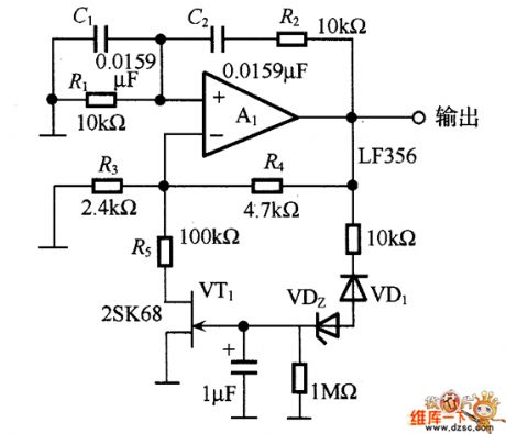
As shown in figure, when it generates low-frequency sine wave, usually it uses the capacitor and resistor to determine the oscillation frequency of RC oscillator circuit. There are many RC oscillator network circuits such as the the Wien bridge oscillator circuit, T-shaped bridge oscillator circuit, phase-shifting oscillator circuit. Figure 6-13 is a Wien bridge oscillator circuit exa,ple, and it is composed of op amp A1 and some capacitors and resistors elements, etc. , and it can obtain the the stable sine wave with the degree of distortion being below 1%.
(View)
View full Circuit Diagram | Comments | Reading(1898)
Triangle wave / square wave output voltage-controlled oscillator circuit diagram
Published:2012/11/11 20:08:00 Author:Ecco | Keyword: Triangle wave, square wave , output, voltage-controlled oscillator
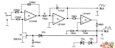
The circuit is composed of the polarity switching circuit, inverting integrator and delay comparator. It uses VT1 switch for polarity switching, the amplifier A1 makes noninverting and inverting work alternately. For example, when VT1 gets conduction, A1 operates for an inverting amplifier. Integrator A2 can integrate the voltage gotten from polarity switching circuit in accordance with the R1 and C1, when points reach Delay comparator's reference voltage, the integrator will reverse and continuously repeat this operation.
(View)
View full Circuit Diagram | Comments | Reading(2534)
| Pages:31/195 At 202122232425262728293031323334353637383940Under 20 |
Circuit Categories
power supply circuit
Amplifier Circuit
Basic Circuit
LED and Light Circuit
Sensor Circuit
Signal Processing
Electrical Equipment Circuit
Control Circuit
Remote Control Circuit
A/D-D/A Converter Circuit
Audio Circuit
Measuring and Test Circuit
Communication Circuit
Computer-Related Circuit
555 Circuit
Automotive Circuit
Repairing Circuit