
555 Circuit
Index 20
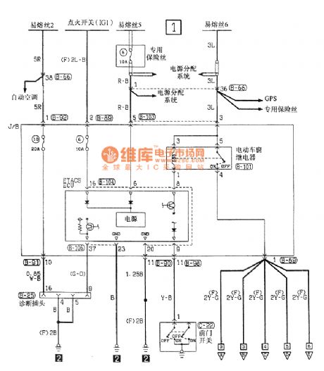
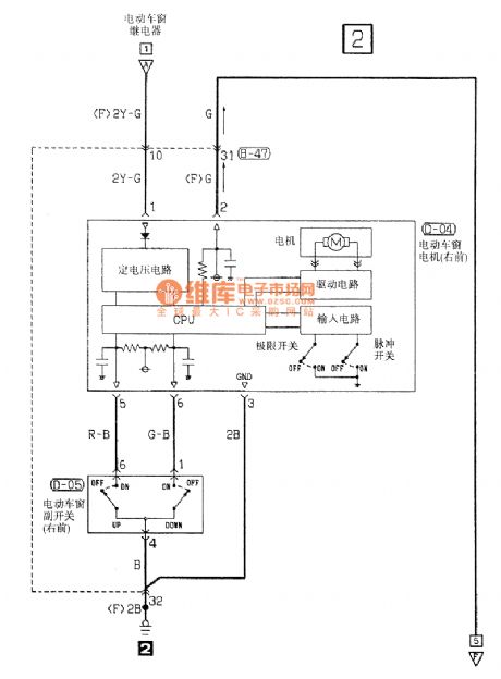
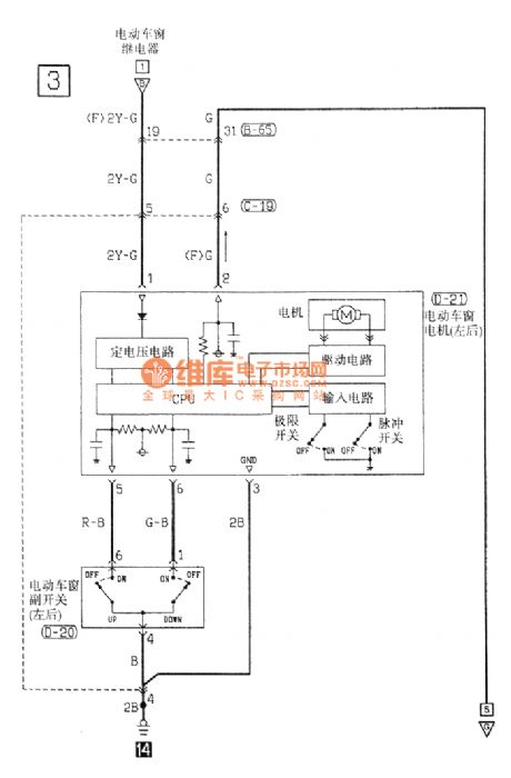
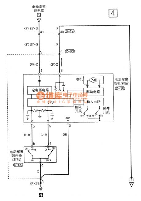
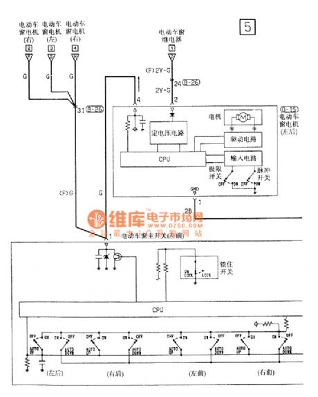
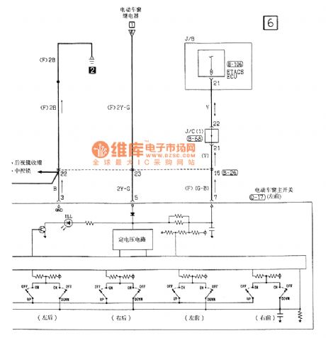
Southeast Soveran power window electrical system circuit
Published:2011/7/12 8:30:00 Author:John | Keyword: power window, electrical system
View full Circuit Diagram | Comments | Reading(972)
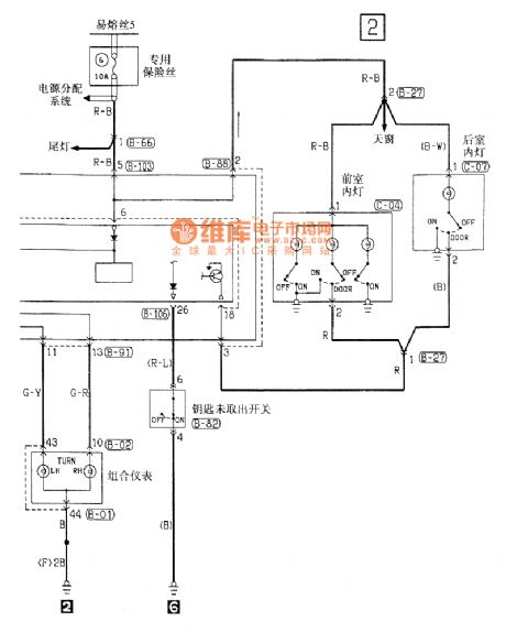
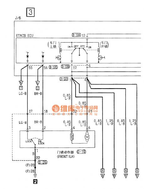
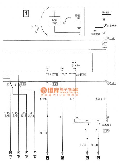
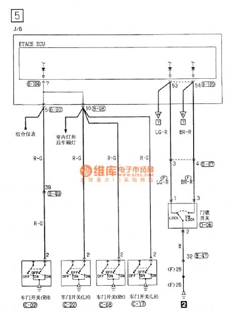
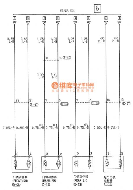
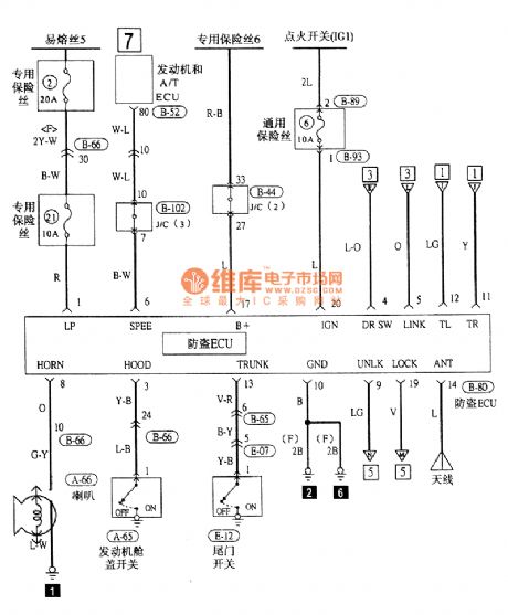
Southeast Soveran central locking and alarming electrical system circuit
Published:2011/7/12 8:34:00 Author:John | Keyword: central locking, alarming, electrical system
View full Circuit Diagram | Comments | Reading(864)
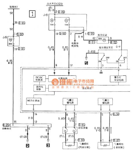
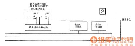
Southeast Soveran airbag electrical system circuit
Published:2011/7/12 8:36:00 Author:John | Keyword: airbag, electrical system
View full Circuit Diagram | Comments | Reading(1038)
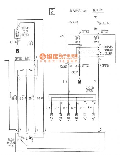
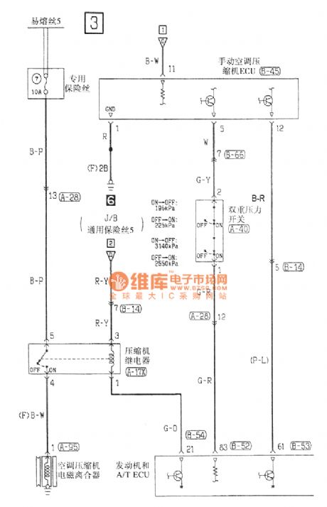
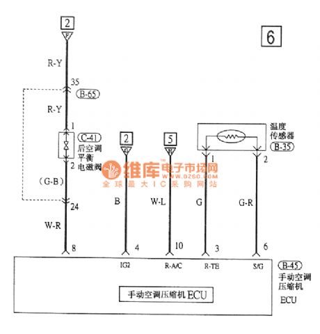
Southeast Soveran manual air-conditioning electrical system circuit
Published:2011/7/12 8:39:00 Author:John | Keyword: manual air-conditioning, electrical system
View full Circuit Diagram | Comments | Reading(899)
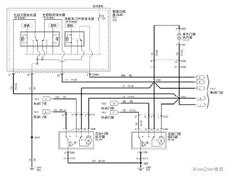
Maverick 2005 electric locks circuit
Published:2011/7/15 2:02:00 Author:Fiona | Keyword: electric locks
View full Circuit Diagram | Comments | Reading(851)
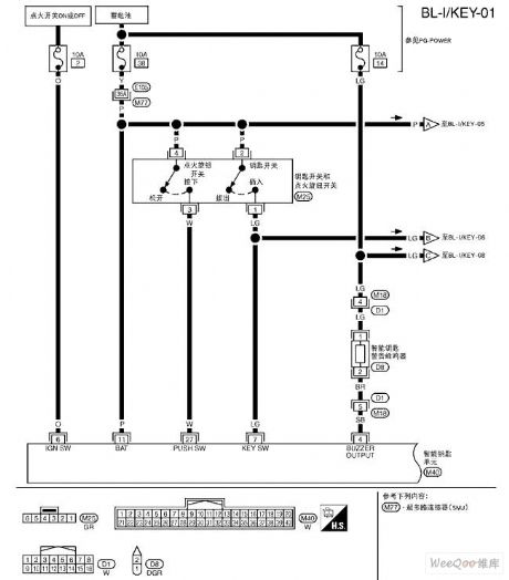
Tiida-BL smart keyless entry system circuit
Published:2011/7/15 2:04:00 Author:Fiona | Keyword: smart keyless entry system
View full Circuit Diagram | Comments | Reading(1209)
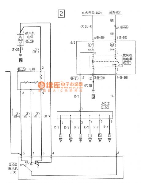
Tiida rear window demister circuit
Published:2011/7/15 1:32:00 Author:Fiona | Keyword: rear window demister
View full Circuit Diagram | Comments | Reading(1059)
Multi-function refrigerator controller composed of 555
Published:2011/5/12 2:20:00 Author:Ecco | Keyword: Multi-function , refrigerator , controller , 555
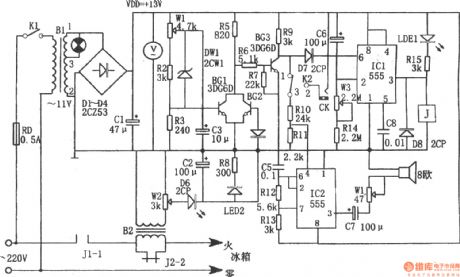
The chart shows the multi-function refrigerator controller. The controller consists of over voltage, under voltage sampling circuit, delay-start circuit, sound and light alarm circuit, buck rectifier circuit. Buck rectifier circuit provides DC voltage for the entire controller. Delay start circuit consists of IC1 (555) and C6, R14, W3, etc, when turning on or getting power after power failure, the terminal voltage of C6 can not be mutated, 555 occurs resetting as pin ⑥ being in high potential, with the charging, C6 makes the potential of pin 2 be less than 1/3VDD, the 555 occurs setting, high output of pin③ makes the relay pull in. The corresponding delay is td = 1.1 (Rw3 + R14) C6, the icon corresponding delay parameter is about 4 to 10 minutes. Overvoltage, undervoltage and overcurrent detection, switch circuit consists of W1, R2, R3, DW1, BG1, BG2, BG3 and so on. When occurring overvoltage, undervoltage or over-flow, BG3 is off, its collector is in high potential, the potential is added to the pin ⑥ of IC1, and 555 resets, the low output of pin ③ makes the relay J release, contact J2-2 cut off, the power of the refrigerator cut off, while LED1 is lit; the other way, the partial pressure passing the R10, R1 added to the pin ④, of IC2, IC2 starts oscillation. (View)
View full Circuit Diagram | Comments | Reading(2066)
555 IC automatic battery charger circuit diagram(2)
Published:2011/5/11 4:06:00 Author:Ecco | Keyword: 555, IC , automatic , battery charger
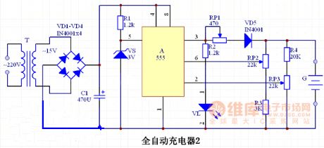
RS flip-flop is composed of A 555 circuit, The two internal comparator reference voltage is supplied by external regulator VS commected to pin 5, so the reset level of circuit is VS's regulator value, which is 3V. The seting circuit of the upper limit charge voltage is composed of the resistor R3 and potentiometer RP2; The seting circuit of the lower limit charge voltage is composed of potentiometer RP3 and resistor R4. The power supply is stepped-down by the T transformer, rectified by diodes VD1 ~ VD4 and filtered by capacitors C1.VD1 ~ VD5 use IN4001 rectifier diodes. VS selects 3V, 1/2W Zener diode, such as UZ-3.0B, IN5226. VL uses an ordinary red LED. RP selects 2W wirewound potentiometer; RP2, RP3 use an ordinary small-scale synthesis of carbon potentiometer, such as WH5; R1 ~ R4 select 1/8W carbon film resistors. C1 selects CD11-25V aluminum electrolytic capacitor. T uses 220V/15V, 5VA small, high quality power transformer.
(View)
View full Circuit Diagram | Comments | Reading(7372)
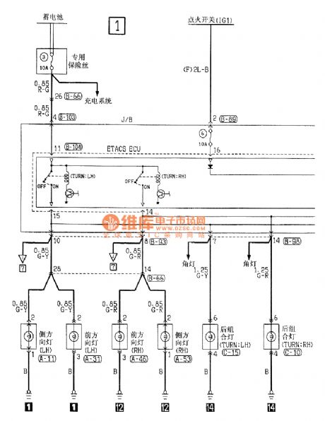
The lighting system, turn and danger alarm signal circuit of Santana 2000 (see as figure 1 and 2)
Published:2011/7/13 22:00:00 Author:Borg | Keyword: lighting system, danger alarm signal, Santana 2000
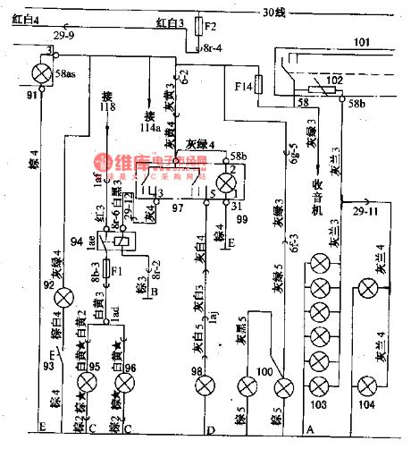
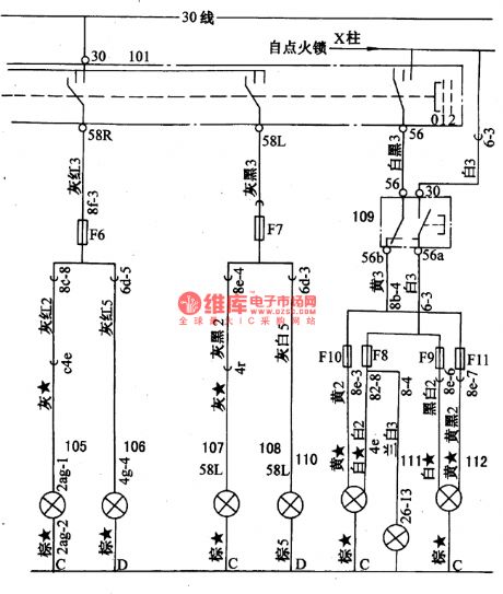
Figure 1. the fog lamp and lighting circuit of Santana 2000 (gasoline injection engine)91-lighting lamp in alarm lamp switch; 92-tool box lighting lamp; 93-tool box lamp switch; 94-fog relay; 95-fog lamp (left); 96-fog lamp (right); 97-fog lamp switch; 98-fog lamp (rear); 99-fog switch lighting lamp; 100-license lamp; 101-general switch; 102-instrument dimming resistor; 103-instrument lighting lamp.
Figure 2. the lighting and front light circuit of Santana 2000 (gasoline injection engine) (View)
View full Circuit Diagram | Comments | Reading(910)
The main parameters of the AC generator
Published:2011/7/11 21:13:00 Author:Borg | Keyword: main parameters, AC generator
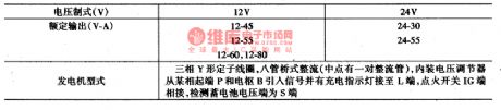
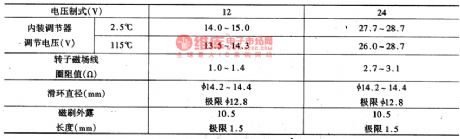
AC generatorThe main parameters of the AC generator are shown in figure 3, the structure of the AC motor is shown in Figure 1.
(View)
View full Circuit Diagram | Comments | Reading(891)
The main technology parameters of the battery
Published:2011/7/11 21:28:00 Author:Borg | Keyword: technology parameters, battery
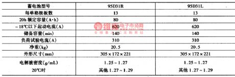
(2) the main features of the power supply starting system1.batteryThe main technology parameters of the battery are shown in figure 2.
(View)
View full Circuit Diagram | Comments | Reading(832)
The the main tech parameters of the diesel engine
Published:2011/7/11 21:54:00 Author:Borg | Keyword: tech parameters, diesel engine
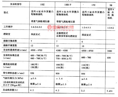
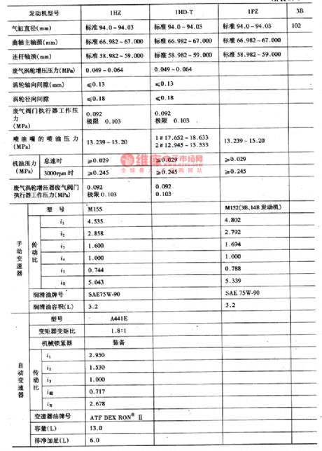
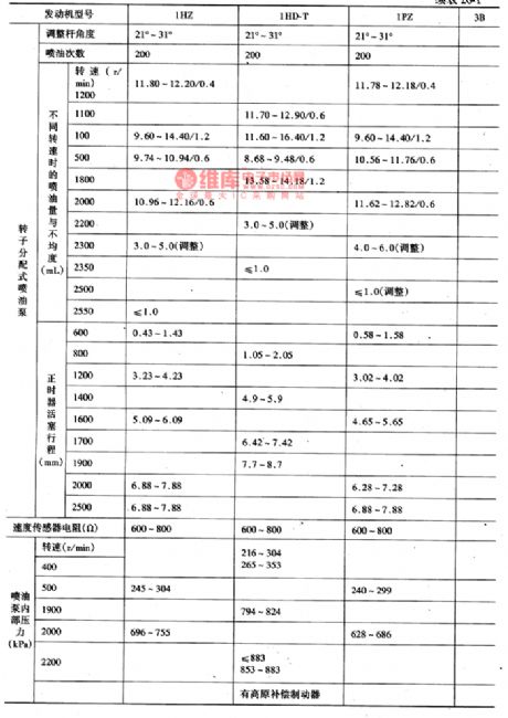
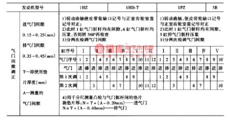
The medium-sized bus of Coster (or Cruise) produced by Toyota takes a large share of Chinese market, of which the ones imported in 80s are gasoline cars, such as RB10, RB11 and BB1O; and the ones imported in 90s are almost diesel cars, such as PZJ(HZJ)70/73/75,HDJ80, HZB30 and HDB30. (1) the main parameters of the engineThe Coster are installed with the 1PZ 5-cylinder diesel engine or 1HZ and 1HD-T 6-cylinder engine, the main parameters are shown in figure 1.
(View)
View full Circuit Diagram | Comments | Reading(1029)
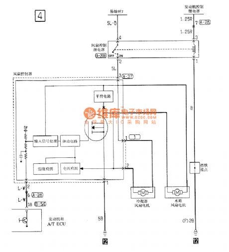
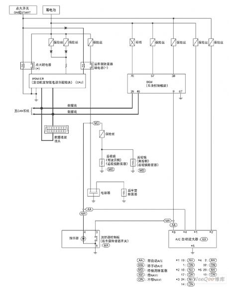
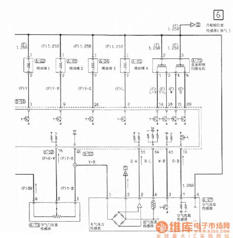
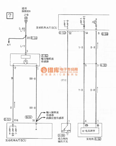
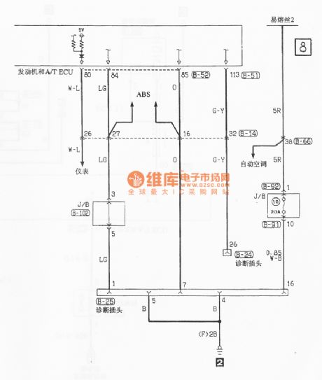
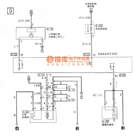
Southeast Soveran motor control circuit
Published:2011/7/12 9:36:00 Author:John | Keyword: motor
View full Circuit Diagram | Comments | Reading(886)
555 storage battery protector circuit with stable voltage charging circuit
Published:2011/6/13 23:24:00 Author:nelly | Keyword: storage battery, protector, stable voltage, charging circuit
As shown in the figure 10-22, the protector circuit is composed of two three-terminal voltage stablizing units and two 555, it includes charge protection and discharge protection. It has the functions of overcharge protection, steady voltage charge, over-discharge protection and short circuit protection.
The charge protection circuit is made of IC1(555)and 7812, 7815 three-terminal regulators. 7812 provides 555 circuit with stable +12V voltage. When it is just charging, the storage battery is charged by J1-1 normally-closed contact. (View)
View full Circuit Diagram | Comments | Reading(924)
555 charging circuit used in the silver-cadmium battery
Published:2011/6/14 2:53:00 Author:nelly | Keyword: silver-cadmium battery, charging
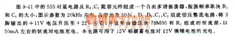
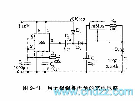
As shown on the figure 9-41, the 555 time base circuit and R1,C1 make up a freedom multivibrator. The oscillation frequency depends on the R1 and C1. The value is about 20KHz on the figure, the duty ratio is 50%. The voltage multiplying rectifier circuit consists of the D1,D2,C1,C2. Steping up the the 3 foot output voltage +11v to +12v and transporting to the constant current source which consists of the voltage stablizing unit 78M05 and R2. Using the constant current 50mA to charge the battery. This circuit can be used in that the 12v lead-acid battery charges the 12v Ni-Cd battery.
(View)
View full Circuit Diagram | Comments | Reading(1595)
555 high/low voltage monitor circuit 1
Published:2011/6/14 2:53:00 Author:nelly | Keyword: high/low voltage, monitor
As shown in the figure 9-17, the input voltage VDD is stabilized voltage supply, it requires hypotension outputs steady voltage, the load current reaches dozens of mA. The actable multivibrator is made of IC1 and R1, R2, C1, the oscillation frequency is f=1.44/ (R1+2R2)C1, generally speaking, the oscillation frequency should be about 10KHz. The pulse width modulator is composed of IC2 and R3, R4, C2, the filter smoothing circuit consists of L, C3, it makes the hgih duty ratio square wave smooth which is exported by IC2, the output voltage Vo is fed back and added to the control terminal of IC2, the width is modulated constantly.
(View)
View full Circuit Diagram | Comments | Reading(1440)
555 DC isolation converter circuit
Published:2011/6/14 2:53:00 Author:nelly | Keyword: DC isolation, converter
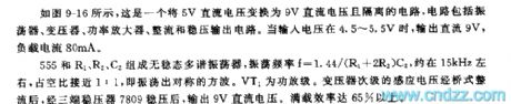
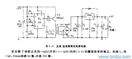
As shown on the figure 9-16, this is an isolation circuit that change the 5v DC voltage to the 9v DC voltage. The circuit includes an oscillator,a transformer, a power amplifier, rectifier and steady voltage output circuit. When the input voltage is between 4.5v and 5.5v, the output DC is 9v and the load current is 80mA. The actable multivibrator consists of the 555 and R1,R2,C2. The oscillation frequency: f=1.44/(R1+2R2)C2。It is about 15kHz, the duty ratio is close to 1:1. The VT1 is a power amplifier. The secondary transformer's induced voltage will output 9v DC voltage through the bridge rectifier and three terminal regulator. The full-efficiency can reach 65%.
(View)
View full Circuit Diagram | Comments | Reading(3831)
Digitally-controlled 555 Astable Multi-vibrator
Published:2011/7/4 22:05:00 Author:Zoey | Keyword: Digitally-controlled, 555 Astable Multi-vibrator
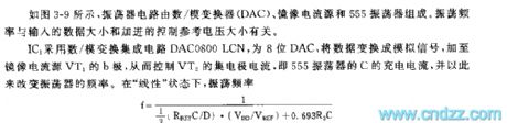
As shown in the figure 3-9, the vibrator circuit consists of anA/D converter, mirror current source, and a 555 oscillator. The scillation frequency is related to the data input and the controllable reference voltage added.
IC1 uses anA/D converter to transform the integrated circuit DAC0800LCN, an eight-digit DAC, and to transform the data to ananlog signal and add it to the b-pole of the mirror current source,so as to control thecollector current,orthe charge current of C in 555 oscillator, to change the frequency of the oscillator.when inlinearity condition, oscillator frequency
f=1/1/3(RpefC/D). (VDD/Vref)+0.693R3C (View)
View full Circuit Diagram | Comments | Reading(1039)
555 Bootstrap Sawtooth wave Generator Circuit
Published:2011/7/4 21:59:00 Author:Zoey | Keyword: 555 Bootstrap , Sawtooth wave, Generator Circuit
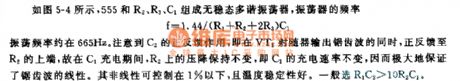
As shown in the figure 5-4, the 555, R2, R3 and C1 constitute a Bi-stable multi-vibrator,the frequency of the Bi-stable multi-vibrator f=1.44/ (R1+R2+2R3)C1 and the oscillation frequency is about 665Hz. Much attention should paid on the positive feedback effect of C2, that is, at the same time that emitter follower VT1 outputs sawtooth wave, the positive feedback goes to the upside of R2.Therefore, the pressure drop on R2 remains unchanged, that means the charge rate of C1 remains unchanged, too. Thus, the linearity of the sawtooth wave is greatly guaranteed. Nonlinearity can be limited to below 1% with excellent temperature stability, generally, it is chose under the condition R1C2>10R2C1. (View)
View full Circuit Diagram | Comments | Reading(1102)
| Pages:20/47 1234567891011121314151617181920Under 20 |
Circuit Categories
power supply circuit
Amplifier Circuit
Basic Circuit
LED and Light Circuit
Sensor Circuit
Signal Processing
Electrical Equipment Circuit
Control Circuit
Remote Control Circuit
A/D-D/A Converter Circuit
Audio Circuit
Measuring and Test Circuit
Communication Circuit
Computer-Related Circuit
555 Circuit
Automotive Circuit
Repairing Circuit