
555 Circuit
Index 14
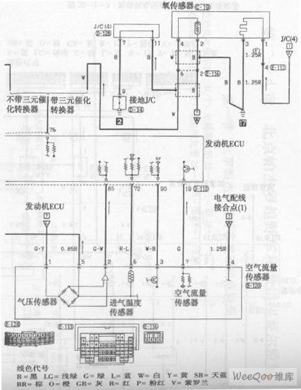
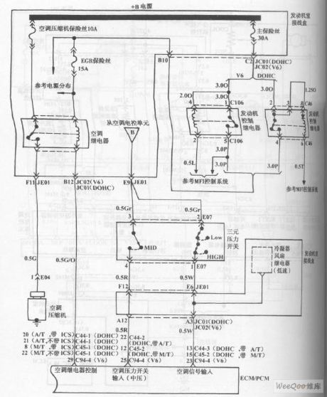
Beijing Pajero SUV Engine Control System (M / T) Circuit (the 5th)
Published:2011/7/18 0:10:00 Author:Felicity | Keyword: Beijing Pajero SUV Engine Control System (M / T) Circuit (the 5th)
View full Circuit Diagram | Comments | Reading(804)
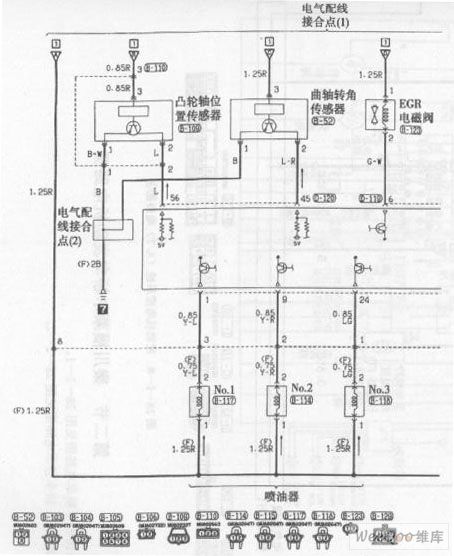
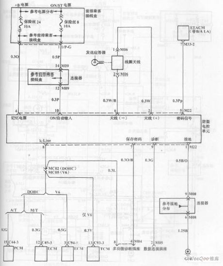
Beijing Pajero SUV Engine Control System (A / T) Circuit (the 1st)
Published:2011/7/18 0:13:00 Author:Felicity | Keyword: Beijing Pajero SUV, Engine Control System (A / T), Circuit, (the 1st)
View full Circuit Diagram | Comments | Reading(827)
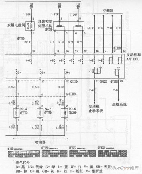
Beijing Pajero SUV Engine Control System (A / T) Circuit (the 2nd)
Published:2011/7/18 0:14:00 Author:Felicity | Keyword: Beijing Pajero SUV, Engine Control System (A / T), Circuit, the 2nd)
View full Circuit Diagram | Comments | Reading(799)
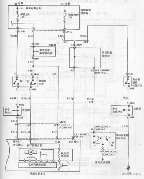
Hyundai Sonata Car Cruise Control Circuit (the 2nd)
Published:2011/7/18 3:15:00 Author:Felicity | Keyword: Hyundai Sonata Car, Cruise Control, Circuit, (the 2nd)
View full Circuit Diagram | Comments | Reading(1076)
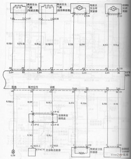
Hyundai Sonata Car Airbag System Circuit (the 3rd)
Published:2011/7/18 3:20:00 Author:Felicity | Keyword: Hyundai Sonata Car, Airbag System, Circuit, (the 3rd)
View full Circuit Diagram | Comments | Reading(1156)
Hyundai Sonata Car Airbag System Circuit (the 2nd)
Published:2011/7/18 3:19:00 Author:Felicity | Keyword: Hyundai Sonata Car, Airbag System, Circuit, (the 2nd)
View full Circuit Diagram | Comments | Reading(916)
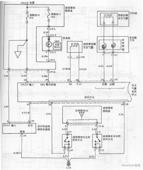
Hyundai Sonata Car Airbag System Circuit (the 1st)
Published:2011/7/18 3:17:00 Author:Felicity | Keyword: Hyundai Sonata Car, Airbag System, Circuit, (the 1st)
View full Circuit Diagram | Comments | Reading(1598)
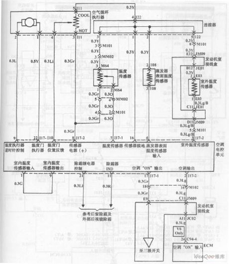
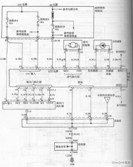
Hyundai Sonata Car Blower And Air Conditioning Control System (Automatic) Circuit (the 4th)
Published:2011/7/18 4:46:00 Author:Felicity | Keyword: Hyundai Sonata Car, Blower And Air Conditioning, Control System, (Automatic), Circuit, (the 4th)
View full Circuit Diagram | Comments | Reading(1410)
Hyundai Sonata Car Blower And Air Conditioning Control System (Automatic) Circuit (the 3rd)
Published:2011/7/18 4:44:00 Author:Felicity | Keyword: Hyundai Sonata Car, Blower And Air Conditioning, Control System, (Automatic), Circuit, (the 3rd )
View full Circuit Diagram | Comments | Reading(1597)
Hyundai Sonata Car Blower And Air Conditioning Control System (Automatic) Circuit (the 2nd)
Published:2011/7/18 3:24:00 Author:Felicity | Keyword: Hyundai Sonata Car, Blower And Air Conditioning, Control System, (Automatic), Circuit, (the 2nd)
View full Circuit Diagram | Comments | Reading(1331)
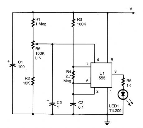
Temperature range controller circuit diagram composed of 555
Published:2011/6/27 5:06:00 Author:Rebekka | Keyword: Temperature range controller
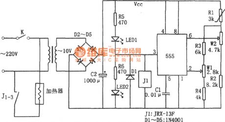
When the temperature falls below the lower temperature, the resistance R1 becomes larger, so that 555 ② feet is lower than the potential 1/3Vcc. The corresponding 555 sets, ③ pin outputs high level. The light-emitting diode LED2 is lit, the relay J1 is pulled in. Connect J1-3 to the heater power supply to heat. When the temperature reaches the maximum temperature. The R1 resistance becomes smaller. The potential of 555 ⑥ will be greater than feet 2/3Vcc. The ② the foot of the potential must be greater than 1/3Vcc, reset the corresponding 555, ③ pin outputs low level. The light-emitting diodes LED1 is lit, the relay J1 releases, the contact J1-3 is disconnected. (View)
View full Circuit Diagram | Comments | Reading(1367)
DUAL_FLASHER_ADD_ON_FOR_555_CIRCUITS
Published:2009/6/19 2:44:00 Author:May

A pair of hex FETs drive two incandescent lamps in an altemating flasher circuit. The lamps can be 12-V automotive types, etc. (View)
View full Circuit Diagram | Comments | Reading(1025)
555 micro defibrillation emergency device circuit
Published:2011/5/2 22:51:00 Author:May | Keyword: 555, micro, defibrillation, emergency device
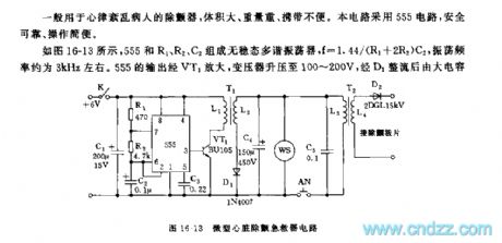
The defibrillator ordinary used for arrhythmia patient is bulky, heavy and inconvenient to carry. This circuit adopts 555 circuit, it is safe and reliable, and the operation is simple.
As shown in diagram 16-13, astable multivibrator consists of 555 and R1, R2, c2, f=1.44/(R1+2R2)C2, its oscillation frequency is about 3kHz. Output of 555 is enlarged by VT1, transformer can set up to 100~200V, it is rectified by D1 and stored energy by big capacitor C3. When using and pressing AN, C4 discharges by the primary stage L3 of T2, and the secondary stage L4 is induced high voltage 1000~7000V and defibrillation for arrhythmia patient.
(View)
View full Circuit Diagram | Comments | Reading(2955)
555 electronic storage device
Published:2011/5/2 22:54:00 Author:May | Keyword: 555, electronic, storage device
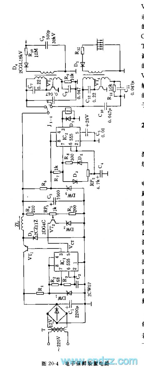
As shown in diagram 20-4, electronic storage device consists of constant voltage source, oscillator, negative-ion generator and ozone generator.
Constant voltage source adopts 555 and R2, R3, C2, etc to make up astable multivibrator, VT1 is switching regulating pipe, R4, RP1, R5 and VT2, etc make up sampling amplifier, it controls pin 5 of IC1, it can automaticly adjust 555's output pulse duty factor, thereby it can achieve the purpose of voltage regulation. D1 is fly-wheel diode. IC2 and R7, R8, RP2, C4, etc make up duty factor adjustable multivibrator type oscillator, oscillation period T=0.693(R7+R8+RP2)C4. The feature of this circuit is: when RP2 is adjusted, it not changes its oscillation frequency and only changes the duty factor of waveform. When pin 3’s output is high level, J pulls in, it makes negative-ion generator composed of VT4, etc to energized and worked. When output of 555 is low level, J is released, J1-1 is connected power supply of ozone generator, it can make the two work in turns, the released ozone and negative-ion can keep vegetables and fruits fresh. (View)
View full Circuit Diagram | Comments | Reading(1289)
555 AC voltage regulator delay and over-voltage alarm circuit
Published:2011/5/13 5:00:00 Author:May | Keyword: 555, AC voltage regulator, delay over-voltage alarm
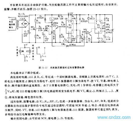
This set has the function of over voltage self protection. When AC voltage regulator works abnormally and output voltage is too high, it can realize automatic displaying, alarming and cutting off high voltage, as shown in diagram 21-17.
This circuit consists of high voltage delay circuit, over voltage detect, alarming circuit and output control circuit.
High voltage delay circuit: delay oscillation circuit consists of 555 and R7, C4, etc. When itis AC power supplied, the voltage on C4 can not break, pin 2 voltage is low level, meanwhile pin 3 of 555 oscillator is high level, it makes VT1 break over, relay Jo pulls in, DC high voltage of constant voltage source is cut off. Due to high capacity capacitor C4 charges, after about 1 minutes, voltage on capacitor is higher than 1/3Vdd, 555's output end (pin 3) changes to low level because circuit wraparound, and VT1 is cut off, Jo's touch spot Jo-1 and Jo-2 are reset, high voltage is turned on, red indicator is lit.
Over voltage detection, alarming circuit: multivibrator type oscillator consists of IC2, R10, RP2, C6, etc. When the voltage of over voltage protection signal thattaken out fromvoltage divider composed of R1, RP1 and R2 exceed given value, controlled silicon SCR breaks over, Jo is pull in, and it can cut off the high voltage of regulated power supply. At the same time, VT1 breaks over, pin 1 of 555 circuit is connected with power supply ground, 555 is Oscillating. Oscillating frequency can adjust by RP2. Sound signal sends out by piezoceramic buzzers.
Output control circuit: it consists of controlled silicon SCR, relay Jo, D7, etc. (View)
View full Circuit Diagram | Comments | Reading(2095)
555_BASED_RAMP_GENERATOR
Published:2009/6/17 2:43:00 Author:May
This circuit is used to generate a ramp voltage for tuning a radio receiver. An NE555, running at about 0.1 Hz, is used as an astable multivibrator. (View)
View full Circuit Diagram | Comments | Reading(2450)
NEON_LAMP_DRIVER_FOR_9_V_SUPPLIES
Published:2009/6/17 2:13:00 Author:May
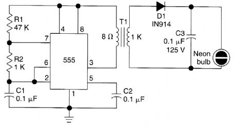
This circuit is for driving a neon lamp from a 9-V supply. The 555 generates an ac signal (stepped up by T1), and lights the neon bulb. T1 is any small audio output transformer. (View)
View full Circuit Diagram | Comments | Reading(4122)
SUPPLY_VOLTAGE_MINITOR
Published:2009/6/17 1:38:00 Author:May
When supply voltage exceeds a preset level, the 555 oscillates, and flashes LED1. The flash rate is controlled by varying C3. (View)
View full Circuit Diagram | Comments | Reading(953)
555_MISSING_PULSE_DETECTOR
Published:2009/6/15 22:26:00 Author:May
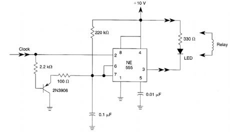
This missing pulse detector can use an LED or relay output. (View)
View full Circuit Diagram | Comments | Reading(2459)
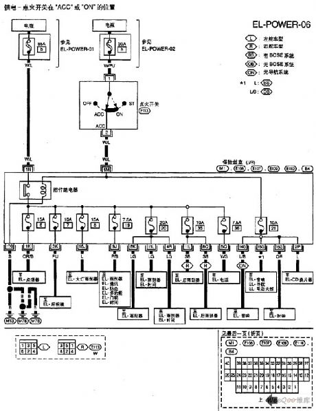
Nissan A32-EL Power Supply Circuit (7)
Published:2011/7/15 5:22:00 Author:Sue | Keyword: Nissan, Power Supply
View full Circuit Diagram | Comments | Reading(911)
| Pages:14/47 1234567891011121314151617181920Under 20 |
Circuit Categories
power supply circuit
Amplifier Circuit
Basic Circuit
LED and Light Circuit
Sensor Circuit
Signal Processing
Electrical Equipment Circuit
Control Circuit
Remote Control Circuit
A/D-D/A Converter Circuit
Audio Circuit
Measuring and Test Circuit
Communication Circuit
Computer-Related Circuit
555 Circuit
Automotive Circuit
Repairing Circuit