
555 Circuit
Index 16
Automobile instrument theory circuit of 70 road vehicle of Toyota Land Cruiser
Published:2011/7/16 9:42:00 Author:Sophia | Keyword: Automobile instrument theory circuit, 70 road vehicle of Toyota Land Cruiser
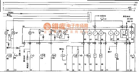
Front and rear windscreen of 70 light-duty off-road vehicles have wiper washing device, and intermittent relay, 103 and 109. The mist grid of Wiper switch 102 is the inching control block, its speed is low.
The figure shows that:
64 is a air filter blocking warning light; 65 is an air filter clogging alarm switch; 66 is a fuel filter alarm buzzer; 67 is a fuel filter warning light; 65 is a fuel filter alarm switch; 69 is a combination the instrument panel; 70 is a four-wheel drive indicator light; 71 is a fourteen-driven light switch; 72a, 72b are turbo indicator; 73a, 73b are turbo indicator switch; 74 is a cancel switch; 75 is a T-belt light; 76 is a bulb check relay; 77 is a vacuum switch (for braking); 78 is a brake fluid level switch; 79 is hand brake switch; 80 is hand brake light; 81 is an oil pressure gauge; 82 is an oil pressure gauge sensor; 83 is a thermometer; 84 is a thermometer sensor; 85 is a fuel gauge; 86 is a fuel gauge sensors; 87 is a voltmeter; 88 is an engine tachometer; 89 is a tachometer sensor; 90 is a speed warning buzzer switch; 91 is a speed warning buzzer; 92 is a speed sensor; 93 is a stop light; 94 is a parking light switch; F7 is a connection from the regulator L column, generators and generator work connected FireWire B-pillar; 162 is a differential lock 4WD electronic control unit terminals No. 8; 23 is an engine electronic control unit; 3 is little fire switch; F6 is a fuse connected from the ignition switch IG1; 27 is point fire coil; 46 is an electronic engine emission control devices; 23 is an engine electronic control unit; 162 is an electronic differential lock control (View)
View full Circuit Diagram | Comments | Reading(1593)
555 shooting game machine circuit
Published:2011/7/18 5:21:00 Author:nelly | Keyword: shooting game machine
The astable multivibrator is composed of IC3 and R5, R6, R3, C5, the oscillation frequency f=1.44(R5+2R6)C5, it is about 1000Hz. At the same time, The output of IC3 is made as the trigger pulse of SCR1~SCR5 by D2, R7. K1~K5 are made into target, when the bullet hits it , the relevant switch is connected, then the relevant SCR is triggered. Only SCR1~SCR5's G pole is triggered in order, LED2~LED6 will light. When IC1's timing time(60s)is ended, IC2 is sealed by the low level which is outputed by 555, IC2 is in forced reset state. At the same time, IC1 chip's discharge lamp is in short-circuit condition, even if it bits the target, SCR will not be triggered and turned on.
(View)
View full Circuit Diagram | Comments | Reading(782)
555 acoustic control electronic cat
Published:2011/7/18 5:23:00 Author:nelly | Keyword: acoustic control, electronic cat
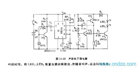
The monostable trigger delay circuit is composed of 555 and RP1, C3. The sudden burst sound(such as clap)is changed into electrical signal by piezoceramics HTD, then it is amplified and added to 555's trigger terminal's 2 foot by VT1. Due to VT1 is saturation conduction, 2 foot's level is lower than 1/3 VDD trigger level, 555 is set, it outputs(3 foot)high level, the audio frequency oscillator obtains electricity and starts to oscillate which is composed of VT2, VT3, L, C4, C5. The oscillation time is decided by 555 monostable delay time td. td depends on the time constant of RP1, C3. After 555 circuit is set, C3 is charged by RP1, when C3's voltage is higher than 2/3 VDD, 555 is reset again, 3 foot turns into low level, the oscillator is no electricity, and it stops oscillating, the cat's noise is stopped.
(View)
View full Circuit Diagram | Comments | Reading(1526)
555 precautionary type electric leakage automatic protector circuit
Published:2011/7/18 5:27:00 Author:nelly | Keyword: precautionary type, electric leakage, automatic protector
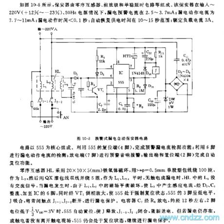
As shown in the figure 10-8, the protector is composed of zero-sequence transformer, preamplifier stage and monostable dalay circuit. In the context of the protector's input is 220V(+12%~-23%), 50Hz, the electric leakage warning current is between 2.5~3.7mA; the electric leakage action current is 7.7~11mA; the electric leakage action time is lower than 0.1s; the automatic recovery power supply time is between 10~15s; the rated load current is 3A.
The circuit is composed as the core of 555. It uses 555's reset terminal(4 foot), then can accomplish the testing function of precautionary current leakage; It uses 6 foot to do the testing of electric leakage; electric discharge terminal(7 foot) does the precautionary audio alarming; the output terminal and set terminal(2 foot)accomplish the automatic reset function.
(View)
View full Circuit Diagram | Comments | Reading(947)
555 musical flashing electronical ball circuit used in the game of passing hydrangea macrophylla
Published:2011/7/18 5:18:00 Author:nelly | Keyword: flashing electronical ball, game, hydrangea macrophylla
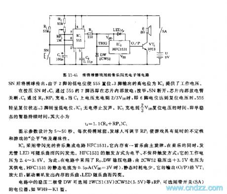
IC1 adopts the time base circuit 555, the monostable delay circuit is composed of IC1, R1, R2, RP1, C1. Before playing the game, the switch SN should be cut off, 555's 2 foot is high level( it is connected to VDD by R1), 555 is in reset state. When playing the hydrangea macrophylla, you must press SN first then pass the hydrangea macrophylla, due to 2 foot's low level, 555 is set, the high level which is outputed by 3 foot provides IC2 with working voltage.
When you arepressing SN, C1 discharges inside the chip by 555's 7 foot; after it, SN cuts off, the chip internal discharge lamp turns off, C1 is charged by R2, RP1, when C1's voltage is charged to 2/3 VDD, namely, 6 foot level reaches resetting voltage, 555 turns to reset state, 3 foot turns to low level, IC2 is no electricity and it stops phonating.
(View)
View full Circuit Diagram | Comments | Reading(1172)
555 Bootstrap Pound wave Genenrator Circuit
Published:2011/7/24 1:03:00 Author:Zoey | Keyword: 555 Bootstrap, Pound wave, Genenrator
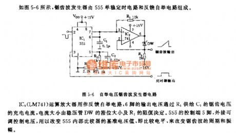
As shown in the figure 5-6, the sawtooth wave generator consists of a 555 single stable circuit and a feedback bootstrap circuit. The IC2 (LM741) operational Amplifier is used as a feedback bootstrap circuit , and the charge current of sawtooth voltage is provided by the output voltage of Pin 6 to C1 through R1, and the current size is determined by the size of the clamp of the voltage regulator tube. The control side of 555 is pin 5, which can adjust and control voltage when attached outside to change the preference voltage of comparator or the comparison level in 555, so that the cycle and amplitude of the sawtooth wave can be changed. (View)
View full Circuit Diagram | Comments | Reading(1184)
555 E-Lark Circuit changing with Light intensity
Published:2011/7/24 0:43:00 Author:Zoey | Keyword: 555 E-Lark Circuit, changes, Light intensity
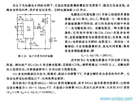
This E-Lark circuit can make a fluctuating and toned sound when exposed in light of different sensitivity, it is like that in the figure 3-22.
The core part of the multi-vibrator is the time-based 555 circuit, which consists of 555, R1, RG and C1.This multi-vibrator concatenates a photoresistance (RG) on its charge and discharge loop, resistance value of this photoresistancewill change as the sensitivity of light changes. This attribute can be used to change the charge and discharge time constant and the frequency of the multi-vibrator, that is, f=1.44/(R1+2RG)C1, GR refers to the photoresistance resistance value in different light sensitivity.
This changeful frequency signal drives the VT1 and makes various bird sounds through the speaker when its current is limited by R2.
We can choose photoresistance series MG41~MG45 used as RG, MG45 is a nonhermetic instrument and its response wave ranges from 0.56 to 0.58μrn, low-power tube 9013 can act as VT1. If you want to strength the vocal power, 8050-type tube can be used. (Pcm=1W,Icm=1.5A, fnt=190MHz)
(View)
View full Circuit Diagram | Comments | Reading(1092)
555 Multi-vibrator with an Adjustable and Independent Charge time
Published:2011/7/24 0:46:00 Author:Zoey | Keyword: 555 Multi-vibrator, an Adjustable and Independent, Charge time
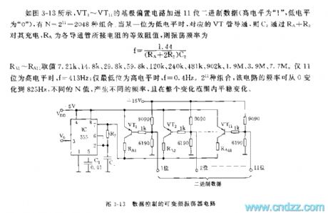
As shown in the picture3-13, base biasing circuit of VT1~VT11 has added 11 binary data, it has 2048 compounding. If any of them becomes low-leveled, the relevant VT pipe will conduct, and C2 charges it through RA+RB, RA refers to the equivalent resistance value of these conduction pipes, its oscillation frequency can be calculated according to the following formula: f=1.44/(RA+2R2)C2
Values of R1~RA1 can be assumed as 7.21k,14.8k,29.8k, 59.8k, 120k, 240k,481k, 902k, 1.9M and 7.7 M. Only when these 11 values are high-leveled, f is equal to 413Hz. If the least significant bit reaches the highest level, f is equal to 0.4Hz. With 2048 mixes, frequency of the circuit ranges from 0~825Hz, different frequencies can be obtained according to different values of N, and the frequencies will change evenly.
(View)
View full Circuit Diagram | Comments | Reading(1106)
555 Non-TransformerDC/It2 Positive Voltage output circuit
Published:2011/7/24 0:45:00 Author:Zoey | Keyword: Non-TransformerDC, Positive Voltage, output circuit
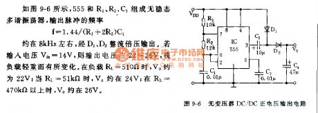
As shown in picture9-6, 555,R1, R2 and C1 constitute an astable multi-vibrator, accordingto the following formula:
f=1.44/(R1+2R2)C1
frequency of output pulse is about 8kHz, and it is output through doubler rectifier D1 and D2. If the input voltage Vin is 14V, then the output voltage ranges from 22V to 26V, the output voltage changes as load change. When load RL is 510Ω, Vo is about 22 V; when it ascends to 51kΩ, Vo is about 24V; and When RL reaches 470kΩ, Vo is about 26V. (View)
View full Circuit Diagram | Comments | Reading(903)
The main sensor circuit of Chevrolet-Lumina (2.2L)
Published:2011/7/13 23:15:00 Author:Borg | Keyword: sensor, Chevrolet-Lumina
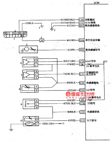
The main sensor circuit of Chevrolet-Lumina (2.2L) 1-internal/earth connection; 2-engine earth connection; 3-disconnector; 4-separating plate wire connector; 5-oxygen sensor; 6-admission pressure sensor; 7-air-conditioner refrigerant; 8-admission temperature sensor; 9-throttle position sensor; 10-coolant temperature sensor; 11-dehydrate temperature lamp (View)
View full Circuit Diagram | Comments | Reading(1470)
TEANA A33-EL Multifunctional Remote Control System Circuit Two
Published:2011/7/15 2:12:00 Author:Joyce | Keyword: TEANA , Multifunctional , Remote Control System
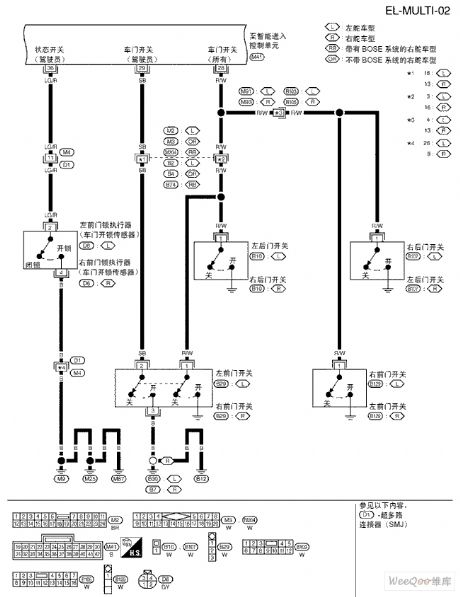
TEANA A33-EL Multifunctional Remote Control System Circuit (View)
View full Circuit Diagram | Comments | Reading(762)
TEANA A33-EL Power Sunroof Circuit
Published:2011/7/15 2:10:00 Author:Joyce | Keyword: TEANA , Power Sunroof
TEANA A33-EL Power Sunroof Circuit (View)
View full Circuit Diagram | Comments | Reading(957)
TEANA A33-EL Multifunctional Remote Control System Circuit One
Published:2011/7/15 2:09:00 Author:Joyce | Keyword: TEANA , Multifunctional , Remote Control System
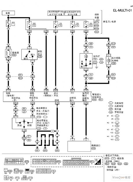
TEANA A33-EL Multifunctional Remote Control System Circuit (View)
View full Circuit Diagram | Comments | Reading(783)
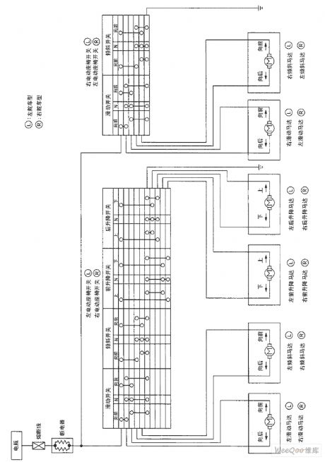
TEANA A33-EL Motor-driven Seats Schematic Diagram and Circuit Two
Published:2011/7/15 2:08:00 Author:Joyce | Keyword: TEANA , Motor-driven , Seats , Schematic Diagram
TEANA A33-EL Motor-driven Seats Schematic Diagram and Circuit (View)
View full Circuit Diagram | Comments | Reading(1005)
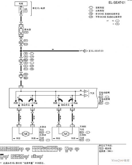
TEANA A33-EL Motor-driven Seats Schematic Diagram and Circuit One
Published:2011/7/15 2:06:00 Author:Joyce | Keyword: TEANA , Motor-driven , Seats , Schematic Diagram
TEANA A33-EL Motor-driven Seats Schematic Diagram and Circuit (View)
View full Circuit Diagram | Comments | Reading(888)
TEANA A33-EL Power Sunroof Circuit Two
Published:2011/7/15 2:04:00 Author:Joyce | Keyword: TEANA , Power Sunroof
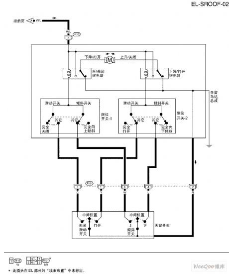
TEANA A33-EL Power Sunroof Circuit (View)
View full Circuit Diagram | Comments | Reading(1052)
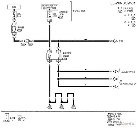
TEANA A33-EL Power Sunroof Circuit One
Published:2011/7/15 2:03:00 Author:Joyce | Keyword: TEANA , Power Sunroof
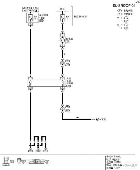
TEANA A33-EL Power Sunroof Circuit (View)
View full Circuit Diagram | Comments | Reading(921)
TEANA A33-EL Door Mirror Circuit Two
Published:2011/7/15 2:02:00 Author:Joyce | Keyword: TEANA , Door Mirror
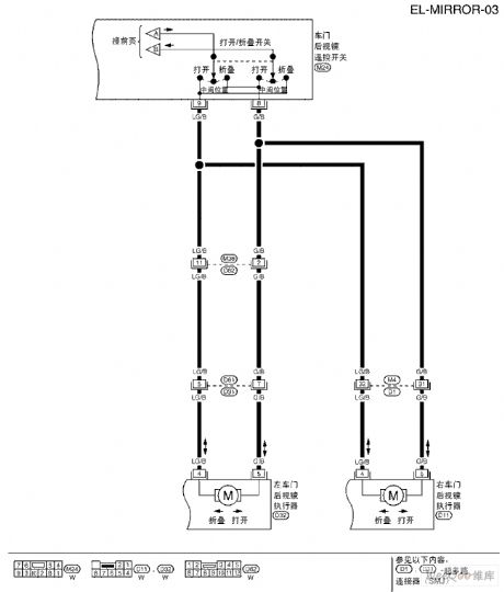
TEANA A33-EL Door Mirror Circuit (View)
View full Circuit Diagram | Comments | Reading(888)
TEANA A33-EL Door Mirror Circuit One
Published:2011/7/15 2:27:00 Author:Joyce | Keyword: TEANA , Door Mirror
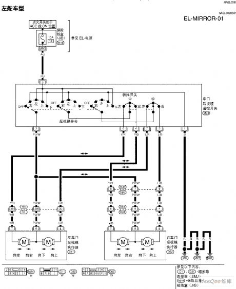
TEANA A33-EL Door Mirror Circuit (View)
View full Circuit Diagram | Comments | Reading(959)
TEANA A33-EL Trunk Lid and Refuel Coupling Door Circuit
Published:2011/7/15 2:34:00 Author:Joyce | Keyword: TEANA, Trunk Lid , Refuel Coupling Door
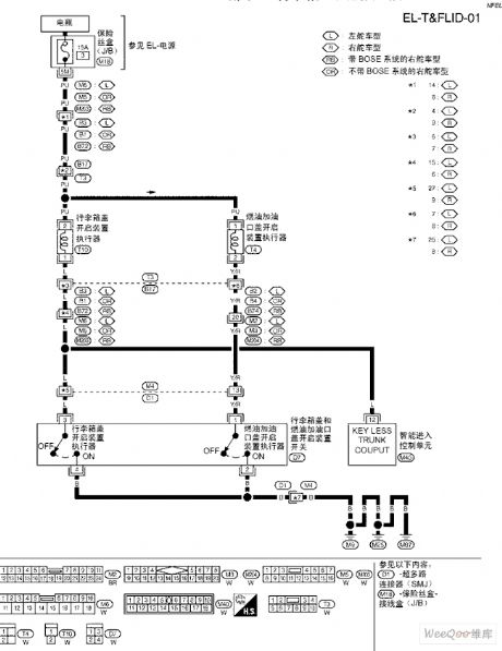
TEANA A33-EL Trunk Lid and Refuel Coupling Door Circuit (View)
View full Circuit Diagram | Comments | Reading(790)
| Pages:16/47 1234567891011121314151617181920Under 20 |
Circuit Categories
power supply circuit
Amplifier Circuit
Basic Circuit
LED and Light Circuit
Sensor Circuit
Signal Processing
Electrical Equipment Circuit
Control Circuit
Remote Control Circuit
A/D-D/A Converter Circuit
Audio Circuit
Measuring and Test Circuit
Communication Circuit
Computer-Related Circuit
555 Circuit
Automotive Circuit
Repairing Circuit