
555 Circuit
Index 13
555_OSCILLATOR_FOR_DRIVING_A_PIEZO_TRANSDUCER
Published:2009/6/24 23:44:00 Author:May
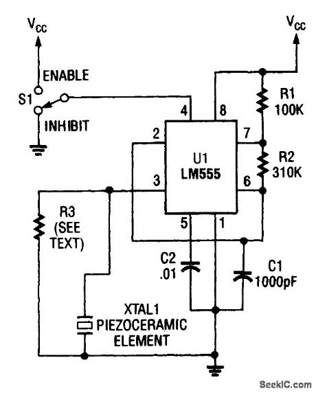
A 555-timer oscillator is perhaps one of the most popular circuits for driving a piezoelectric transducer. (View)
View full Circuit Diagram | Comments | Reading(3226)
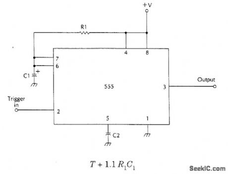
BASIC_555_MONOSTABLE
Published:2009/6/24 22:24:00 Author:May
View full Circuit Diagram | Comments | Reading(883)
LAMP_TIMER
Published:2009/6/24 4:35:00 Author:Jessie

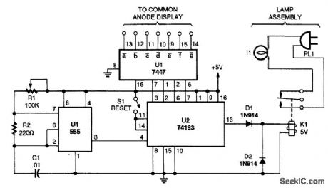
A timed switch uses a 555 oscillator/timer wired to operate in the astable mode. The timer sup-plies a positive pulse to the clock input of a 74193 4-bit binary up/down count every five minutes. Be-cause the 74193 is set to operate in the count-down mode, the output of the 555 is connected to the count-down input of the 74193.As the binary counter is reset, it starts counting at nine and counts down to zero with each clock pulse. When the counter hits zero, the output from the 74193 goes low, tuming off the relay and the light. The light can be tumed back on by pressing the reset button again. (View)
View full Circuit Diagram | Comments | Reading(0)
BASIC_555_ASTABLE_MULTIVIBRATOR
Published:2009/6/24 3:47:00 Author:Jessie
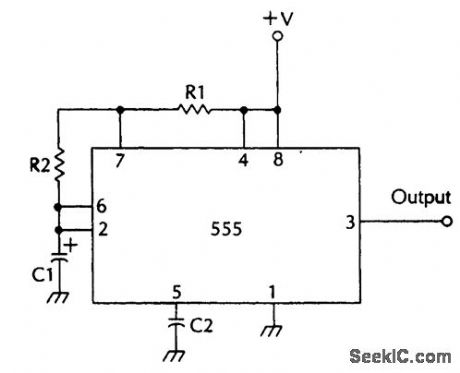
F=1.44(R1=2R2)C1 (View)
View full Circuit Diagram | Comments | Reading(1090)
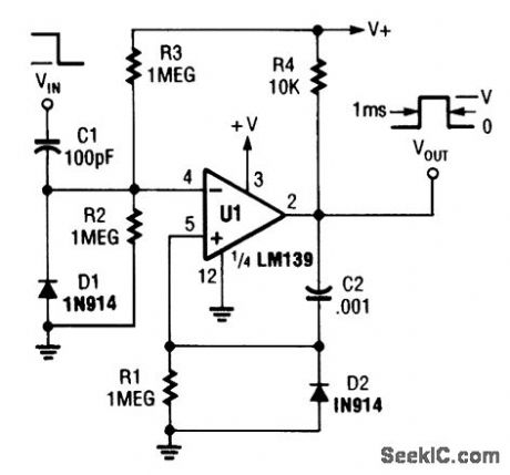
ASTABLE_WITH_VARIABLE_PULSE_WIDTH
Published:2009/6/24 3:44:00 Author:Jessie
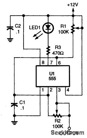
This produces a positive variable width pulse and has a symmetry control. R1 and R2 control the pulse width and symmetry. (View)
View full Circuit Diagram | Comments | Reading(1614)
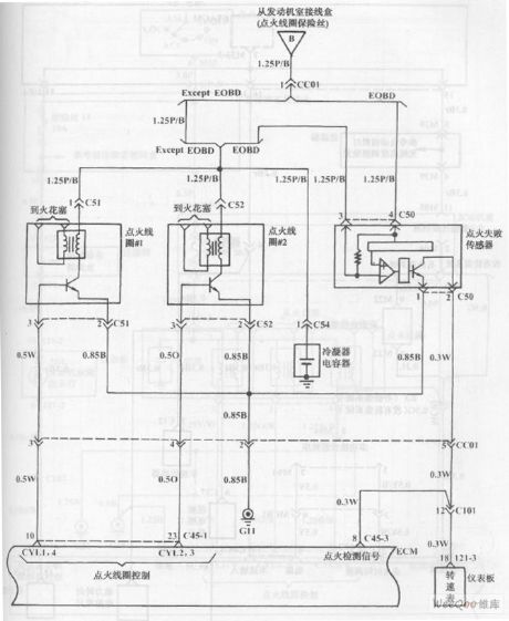
Fuel Injection System Circuit of Hyundai Sonata with 4-Cylinder Engine (8)
Published:2011/7/19 21:51:00 Author:Sue | Keyword: Fuel Injection, Hyundai Sonata, 4-Cylinder
The picture shows the fuel injection system circuit of Hyundai Sonata with 4-cylinder engine. (View)
View full Circuit Diagram | Comments | Reading(877)
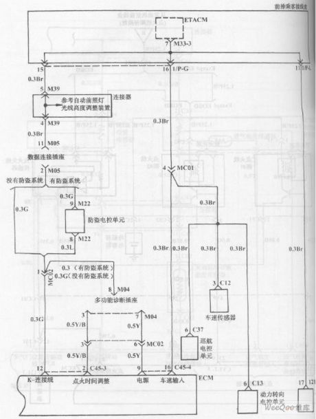
Fuel Injection System Circuit of Hyundai Sonata with 4-Cylinder Engine (7)
Published:2011/7/19 21:51:00 Author:Sue | Keyword: Fuel Injection, Hyundai Sonata, 4-Cylinder
The picture shows the fuel injection system circuit of Hyundai Sonata with 4-cylinder engine. (View)
View full Circuit Diagram | Comments | Reading(1277)
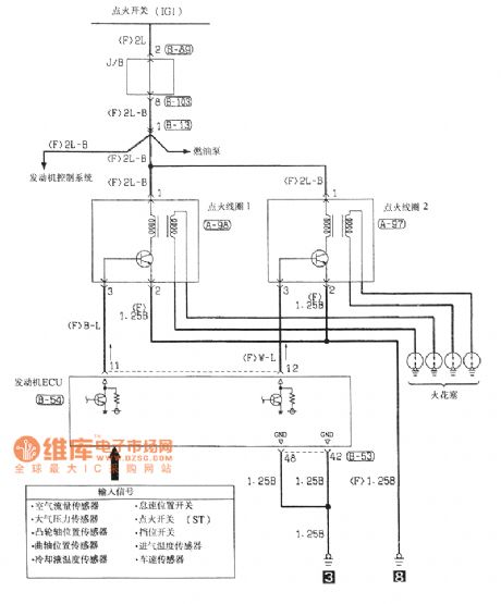
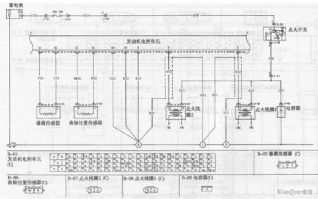
Southeast Soveran ignition system circuit
Published:2011/7/23 9:30:00 Author:John | Keyword: ignition system
View full Circuit Diagram | Comments | Reading(780)
555 long time delay circuit 1
Published:2011/7/29 2:40:00 Author:Ecco | Keyword: 555, long time, delay circuit
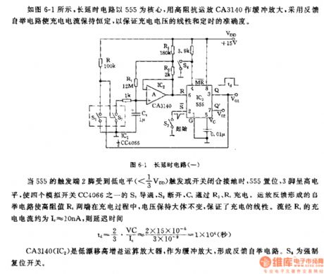
As the figure 6-1 shown, the long time delay circuit uses 555 as the core,it usesa high-impedance op-amp CA3140 buffer amplifier, the feedback bootstrap circuit to maintain a constant charging current, to ensure the accuracy of linear and time of charge voltage.
When the pin 2 of 555 is triggered by the low level or the switch is closed to ground, the 555 sets, pin 3 is in high level, so that one of the four analog switches CC4066 S1 is conducted, S2 turns off, C1 charges through R3, R4. The bootstrap circuit produced by feedback op amp keeps the voltage when the both ends of the high-resistance R1 in the charging process. It ensures a linear charging. The current flowing R4 the charging circuit is about 10mA.
CA3140(IC2) is a high-gain low-drift op amp, it is usedas buffer amplifier, the feedback forms the bootstrap circuit. The S4 is mandatory reset switch.
(View)
View full Circuit Diagram | Comments | Reading(1617)
555 long time delay circuit 2
Published:2011/7/29 2:23:00 Author:Ecco | Keyword: 555, long time , delay circuit
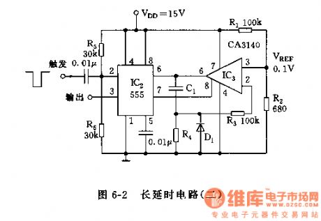
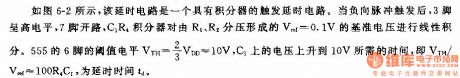
The circuit is shown as the chart 6-2, the delay circuit is a trigger delay circuit with integrator.
CA3140 is a BIMOS single-supply op amp, itcan still work when the value ofVref is very low or zero, and its gate (pin 8)can discharge frompin 7of 555 (through D1). Diode D1is required to the J-FET gate - source PN junction with smaller leakage, the conduction current is high, reverse leakage is small (about 100pA).
As shown in Figure 5-2, the delay circuit is a trigger delay circuit with integrator. When the negative pulse is triggered, the pin 3 is in high level, and pin 7 is in open circuit, then C2R4 integrator makes line integralon the reference voltage Vref = 0.1V divided by the R1, R2.
(View)
View full Circuit Diagram | Comments | Reading(1368)
555_FM_CIRCUIT
Published:2009/6/23 3:12:00 Author:Jessie
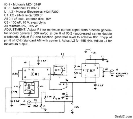
Circuit for applying a dc-coupled FM or PPM to a 555 configured as an oscillator. (View)
View full Circuit Diagram | Comments | Reading(1760)
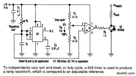
VARIED_REP_RATE_DUTY_CYCLE_WITH_555
Published:2009/6/23 1:57:00 Author:May
View full Circuit Diagram | Comments | Reading(2583)
50%DUTY_CYOLE_555_CIRCUIT
Published:2009/6/23 1:56:00 Author:May
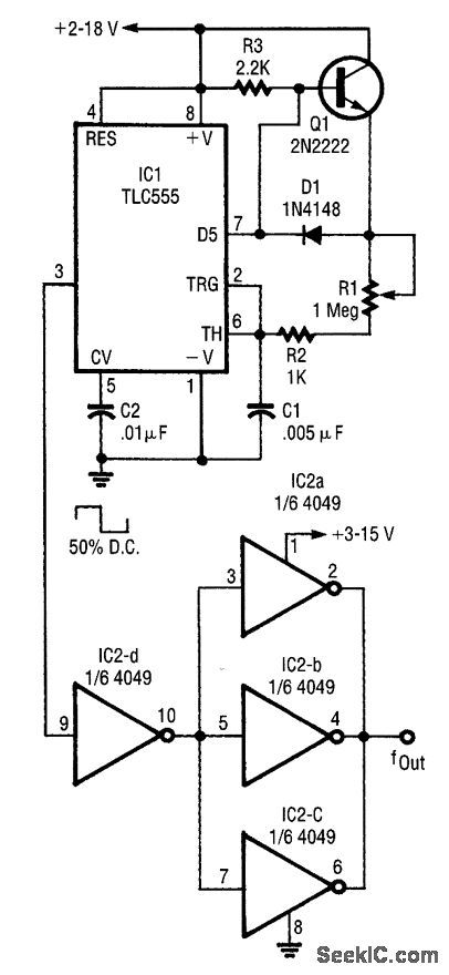
Using an external charge transistor and diode enables a 50% duty cycle and easy frequency control. When the 555's discharge transistor is cut off, the 2N2222 acts as an emitter follower. When the discharge transistor turns on, the 2N2222 turns off and C1 discharges through (R1+R2) at the same rate. The IN4l48 provides temperature compensation. (View)
View full Circuit Diagram | Comments | Reading(1359)
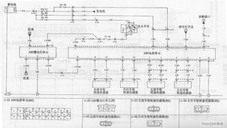
KIA Maxima Sedan ABS Circuit
Published:2011/7/17 23:48:00 Author:Felicity | Keyword: KIA Maxima Sedan, ABS Circuit
View full Circuit Diagram | Comments | Reading(799)
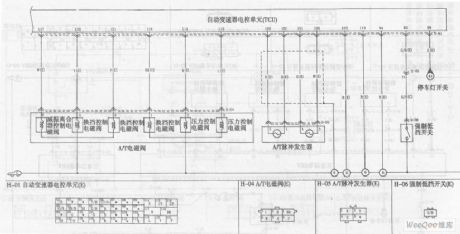
KIA Maxima Sedan Automatic Transmission Circuit (the 2nd)
Published:2011/7/17 23:52:00 Author:Felicity | Keyword: KIA Maxima Sedan, Automatic Transmission Circuit, (the 2nd)
View full Circuit Diagram | Comments | Reading(793)
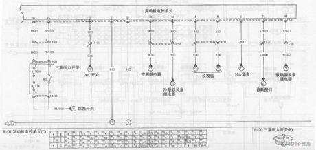
KIA Maxima Car Cooling System Circuit
Published:2011/7/18 0:01:00 Author:Felicity | Keyword: KIA Maxima, Car Cooling System, Circuit

View full Circuit Diagram | Comments | Reading(875)
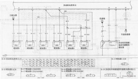
KIA Maxima Car Engine Circuit (the 4th)
Published:2011/7/17 23:59:00 Author:Felicity | Keyword: KIA Maxima Car Engine Circuit (the 4th)
View full Circuit Diagram | Comments | Reading(734)
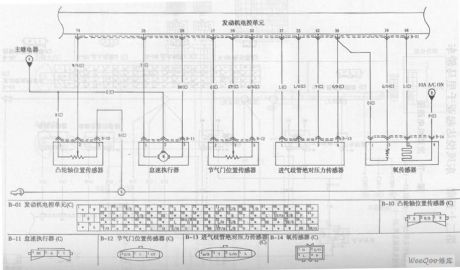
KIA Maxima Car Engine Circuit (the 3rd)
Published:2011/7/17 23:58:00 Author:Felicity | Keyword: KIA Maxima, Car Engine Circuit, (the 3rd)
View full Circuit Diagram | Comments | Reading(773)
KIA Maxima Car Engine Circuit (the 2nd)
Published:2011/7/17 23:56:00 Author:Felicity | Keyword: KIA Maxima, Car Engine Circuit, (the 2nd)
View full Circuit Diagram | Comments | Reading(777)
KIA Maxima Car Engine Circuit (the 1st)
Published:2011/7/17 23:54:00 Author:Felicity | Keyword: KIA Maxima, Car Engine Circuit, (the 1st)
View full Circuit Diagram | Comments | Reading(749)
| Pages:13/47 1234567891011121314151617181920Under 20 |
Circuit Categories
power supply circuit
Amplifier Circuit
Basic Circuit
LED and Light Circuit
Sensor Circuit
Signal Processing
Electrical Equipment Circuit
Control Circuit
Remote Control Circuit
A/D-D/A Converter Circuit
Audio Circuit
Measuring and Test Circuit
Communication Circuit
Computer-Related Circuit
555 Circuit
Automotive Circuit
Repairing Circuit