
555 Circuit
Index 6
Simple 555 Timer Monostable Circuit
Published:2012/9/17 21:41:00 Author:Ecco | Keyword: 555 , Timer, Monostable
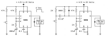
The two circuits below illustrate using the 555 timer to close a relay for a predetermined amount of time by pressing a momentary N/O push button. The circuit on the left can be used for long time periods where the push button can be pressed and released before the end of the timing period. For shorter periods, a capacitor can be used to isolate the switch so that only the initial switch closure is seen by the timer input and the switch can remain closed for an unlimited period without effecting the output. (View)
View full Circuit Diagram | Comments | Reading(2471)
555 vehicle turn signal electronic flasher circuit
Published:2011/11/10 2:58:00 Author:May | Keyword: 555, vehicle turn signal, electronic flasher
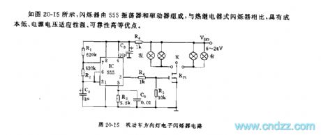
As shown in diagram 20-15,the flasherconsists of 555 oscilator and driver. Comparing with thermorelay scintillator, its advantagesinclude: low cost, strong power supply voltage suitability, high reliability, etc.
555 and R1, R2, C1 make up astable multivibrator, its oscillating frequency is about 1HZ. It adopts VMOS K75 tube as driving switch. When car turns left or right, it can break overto lightthe left or right indicator. (View)
View full Circuit Diagram | Comments | Reading(4267)
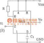
555 basic IC diagram
Published:2011/12/2 2:01:00 Author:Ecco | Keyword: 555, basic IC

View full Circuit Diagram | Comments | Reading(2481)
555 Refrigerator protector circuit 1
Published:2011/10/18 3:45:00 Author:Ecco | Keyword: 555 , Refrigerator protector
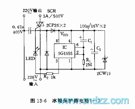
The circuit is shown in Figure 13-6, the circuit is based on 555 circuit to form power delay protection circuit. The connection of C1 makes pin 6 be in high level, and pin 3 be in low level, when the supply is turned again after failure, SCR is cut off. C1 charges, so the pin 2 is lower than the trigger time of 1/3 vdd, that is the delay time td. Icon corresponding td parameter is about 6 minutes. Setting to 555, pin 3 outputs high level. SCR turns on, the refrigerator gets power and the working indicator LED is lit.
(View)
View full Circuit Diagram | Comments | Reading(3438)
555 timer circuit for darkroom 3
Published:2011/10/18 3:44:00 Author:Ecco | Keyword: 555, darkroom , timer circuit

As the figure 17-16 shown, the timing circuit is composed of two branches of 555, IC1 forms a timer, IC2 is a second signal metronome. AN1 is the timer button, clicking the AN1, 555 sets, J pulls in, light exposure lamp H1 is lit, safelight H2 is off. K1 is regular file, when the C1 (or C2) is charged to more than 2/3 threshold level, the 555 resets, J releases. H1 is off, H2 is lit, exposure ended. IC2 and RP2, R4, R5, C4 etc. form astable multivibrator, adjusting the RP2 can make the oscillation be 1Hz. The output of it drives red LED lighting by VT1.
(View)
View full Circuit Diagram | Comments | Reading(2061)
Single-end bistable circuit composed of 555
Published:2011/8/23 21:10:00 Author:Ecco | Keyword: Single-end , bistable circuit , 555
(View)
View full Circuit Diagram | Comments | Reading(1071)
555 simple refrigerator protection circuit
Published:2011/8/2 1:16:00 Author:Ecco | Keyword: 555, simple , refrigerator, protection
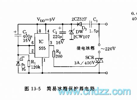
The circuit is shown in Figure 13-5, the protection is mainly used for power delay protection to avoid the compressor from frequent start, and mechanical damage from the non-equilibrium state. When it stops, the voltage on C1 discharges through D1 immediately. When it gets power again, because the voltage on C1 is not mutation, 555 is in the reseting state; until C1 is charged to td = 1.1R1C1, which is about 6 minutes, 2 foot level is below the 1/3 VDD, 555 is set, the SCR then is connected, refrigerator is running.
(View)
View full Circuit Diagram | Comments | Reading(3203)
555 Automatic fan speed controller circuit
Published:2011/8/4 22:00:00 Author:Ecco | Keyword: 555 , Automatic, fan speed , controller
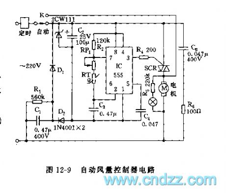
As shown in Figure 12-9, the controller circuit consists of step-down rectifier circuit and an oscillator and control circuit. 555 and R2, RP1, C3 and thermistor RT form a non-steady multivibrator, the oscillation frequency f = 1.44 / (R2 + RP1 +2 RT) C3. It can be shown by the formula, the oscillation frequency is related to RT. When it selects a negative temperature coefficient thermistor, the temperature rises, RT resistance decreases, the oscillation frequency increases, and the duty cycle increases, the motor conduction timeincreases, natural wind increases; or the temperature drops, the power-on time reduces, the natural wind is weaken.
(View)
View full Circuit Diagram | Comments | Reading(3559)
555 Ventilator automatic timing controller circuit
Published:2011/8/4 21:58:00 Author:Ecco | Keyword: 555 , Ventilator, automatic timing , controller
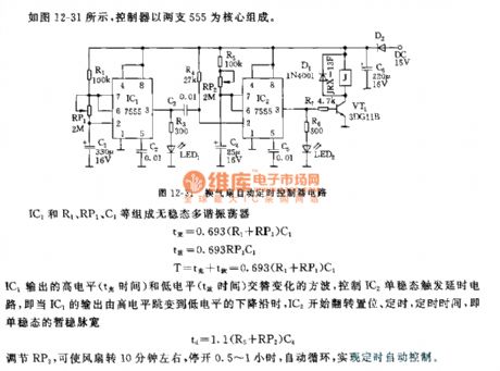
The controller shown as figure 12-31 is based on two roads of 555. IC1 and R1, PR1, C1 etc. form astable multivibrator. IC1 outputs alternating high and low output square wave to control the trigger IC2 monostable delay circuit, that is, when falling delay of IC1's output changes from high to low level, IC2 starts flipping set, timing.Adjusting RP2 can turn onthe fan for about 10 minutes and close 0.5 to 1 hour, it will change in automatic cycle to achieve automatic control of time.
(View)
View full Circuit Diagram | Comments | Reading(1552)
555 voice circuit in fencing
Published:2011/8/4 21:57:00 Author:Ecco | Keyword: 555 , voice circuit , fencing
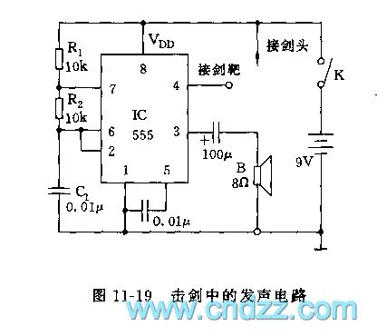
The circuit is shown as figure 11-19, 555 is the core of the circuit. The pin 4 of 555 is the reset terminal, when the voltage is below 0.7V, then the shock ends. The leading wire of pin 4 is connected to metal arrow, if hitting the target is connected to the power (higher than 1.4V) in the game, the 555 circuit will shock, vibration frequency depends on R1, R2, C1's value, that is, f = 1.44 (R1 +2 R2) C1. icon parameter frequency is about 800Hz, if hitting, it will emit sound. If tipis away from the target, the circuit is forced to be in reset state.
(View)
View full Circuit Diagram | Comments | Reading(1358)
555 Voltage monitor circuit
Published:2011/8/4 21:56:00 Author:Ecco | Keyword: 555 , Voltage , monitor
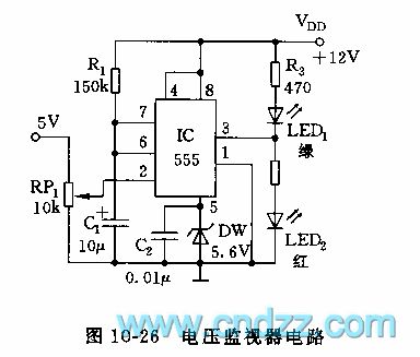
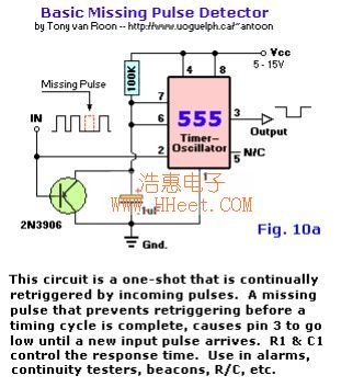
As shown in figure 10-26, the monitoring circuit is an one-shot trigger circuit which is composed of 555 and R1, C1, RP1, DW. Icon monitoring voltage is +5 V, when the input voltage of pin 2 of 555is normal, pin 3 of 555 is in low level, LED1 (green) is lit; if the input voltage is below the seting threshold level, 555 sets, pin 3 is in high level, LED1 is off, LED2 (red) is lit. If the monitor voltageis lower than normal value for a long time, 555 monostable circuit can be continuously re-trigger, that means it will start again after trigger temporary steady state td = 1.1R1C1. Temporary stabilization time of the icon parameter is about 1.7 seconds.
(View)
View full Circuit Diagram | Comments | Reading(3055)
555 Low power, high voltage and low current inverter circuit
Published:2011/8/4 21:55:00 Author:Ecco | Keyword: 555, Low power , high voltage , low current, inverter
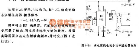
As shown in Figure 9-35, 555 and R1, RP1, C1 form an astable multivibrator, the oscillation frequency f = 1.44 / (R1 +2 R2) C1. The frequency can be adjusted by RP1. Its output is output by the audio step-up transformer T, it may realize the conversion of DC to AC. Selecting the audio output frequency and designing transformer T is according to the actual needs.
(View)
View full Circuit Diagram | Comments | Reading(2562)
555 Inductive battery charging circuit
Published:2011/9/18 21:15:00 Author:Ecco | Keyword: 555, Inductive , battery, charging circuit
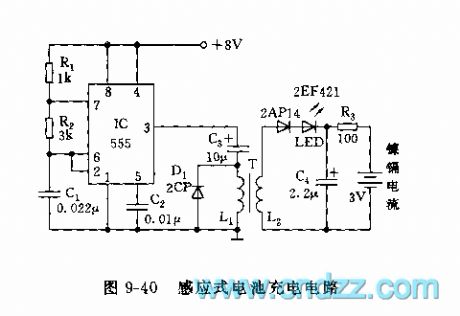
As shown in Figure 9-40, 555 and R1, R2, C1 form an astable multivibrator, f = 1.44/ (R1 +2 R2) C1, the oscillation frequency of the icon parameter is approximately 10kHz. The oscillation square wave is added to the primary L1, secondary L2 of inductively coupled coil, and two nickel-cadmium batteries are mounted in the dielectric plexiglass shell, that is, it uses inductive charging method. The core of coil antenna uses φ10 magnet bar of radio, it uses φ0.13mm and φ0.27mm wires with 200turns on the primary and secondary coils, the middle is cut and connected in the both sides of dielectric plexiglass panels. Battery charging current is up to 10mA, when it is charging, LED is lit.
(View)
View full Circuit Diagram | Comments | Reading(6065)
555 pointer electronic megohmmeter
Published:2011/9/18 21:14:00 Author:Ecco | Keyword: 555 , pointer electronic megohmmeter
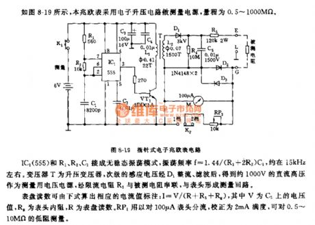
As shown in Figure 8-19, the megohmmeter uses the electronic boost circuit as measuring power, the range is 0.5 ~ 1000MΩ. IC1 and R1, R2, C1 are connected in non-steady-state oscillation mode, and the oscillation frequency f = 1.44 / (R1 +2 R2) C1, it is about 15kHz. Transformer T is the step-up transformer, the secondary induced voltage is rectified by D1, after being filtered, it can get 1000V DC high voltage power supply as measuring voltage, the current limiting resistor R5 and the measured resistor are connected in series and then form measuring loop with header. Dial readings can be calculated by the following formula, the current value of the corresponding label: I = V / (R + R5 + Rg), and V is the voltage on C5, Rg is the internal resistance of meter, R is the dial reading. RP1 header is used for for streaming on the 100μA header, correcting 2mA full-scale, and measuring low resistor with 0.5 ~ 10MΩ.
(View)
View full Circuit Diagram | Comments | Reading(3717)
555 resistance quick measuring circuit
Published:2011/9/18 21:12:00 Author:Ecco | Keyword: 555, resistance quick measuring
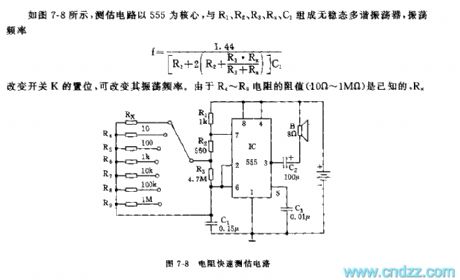
As shown in Figure 7-8, measuring circuit uses 555 as the core, and 555,R1, R2, R3, Rx, C1 form an astable multivibrator.
Changing the switch K can change the oscillation frequency. Since R4 ~ R9 resistor (10Ω ~ 1MΩ) is known, Rx is the resistance under test,it caneasily and quickly determine the resistance of Rx by the comparison of the sound with correspondingoscillation frequency of known resistors.
(View)
View full Circuit Diagram | Comments | Reading(2000)
555 AC timing switch controller circuit
Published:2011/9/18 22:13:00 Author:Ecco | Keyword: 555 , AC, timing switch , controller
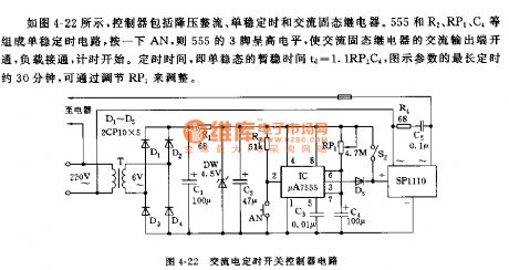
As shown in Figure 4-22, the controller includes the buck rectifier, monostable AC solid relay. And 555 and R1, RP1, C4, etc. form a monostable circuit, clicking the AN, the pin 3 of 555 is in high level, the AC output of AC solid relay turns on, load is connected, timing begins. Regular time is the monostable transient stability time td = 1.1RP1C4, the longest time of icon argument is about 30 minutes, it can be adjusted by RP1.
(View)
View full Circuit Diagram | Comments | Reading(1593)
555 various waveform generator circuit 1
Published:2011/9/18 22:04:00 Author:Ecco | Keyword: 555, various waveform, generator
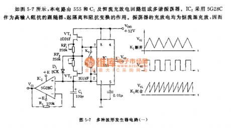
The circuit shown in Figure 5-7 is a multi-vibrator circuit composed of 555 and constant current charging and discharging circuit and C1. IC2 uses 5G28C as a high input impedance follower to play the role of isolation and impedance transformation. Oscillators are constant current charging and discharging, so the sawtooth has a good linearity. RP1, RP2 are used to adjust the charging and discharging time constant and the duty cycle. Icon parameter cycle is 0.2ms ~ 60s. When K1 is closed, it produces sawtooth, of which period is half the triangle wave.
(View)
View full Circuit Diagram | Comments | Reading(2561)
555 Linear voltage / frequency converter circuit 4
Published:2011/9/18 22:03:00 Author:Ecco | Keyword: 555, Linear voltage , frequency , converter
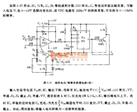
As shown in Figure 5-37, IC1 and R1, C1, D1, etc form integrator, 555 and R2, C2 etc. form monostable trigger. When the input voltage Vi changes in the range of 0 ~ 10V, the 1kHz / V conversion factor of VFC circuit can be transformed into 0 ~ 10kHz frequency. When there being the input signal voltage Vin, IC1 output declines to the trigger level of IC2, 555 sets, VT2 is conducted, D2, D3 are cut off, D1 turns on, VT1 provides constant current andanti-charge for C1. IC1's output voltage rises. At this point, IC2 monostable timing capacitor C2 charges to 2/3 VDD threshold level, the 555 resets, VT2 is off, D2, D3 are conducted, D1 closes, the input voltage is converted to a certain frequency of oscillation again and again.
(View)
View full Circuit Diagram | Comments | Reading(1608)
555 Linear voltage / frequency converter circuit 3
Published:2011/9/18 21:48:00 Author:Ecco | Keyword: 555, Linear voltage , frequency , converter
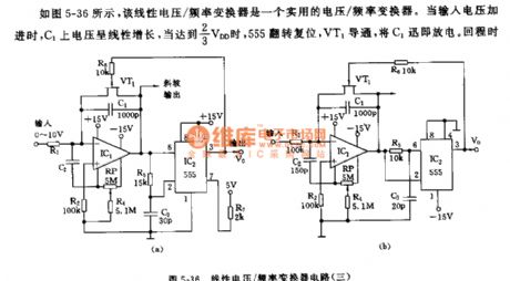
As shown in Figure 5-36, the linear voltage/frequency converter is a practical voltage/frequency converter. When added to the input voltage, the voltage on C1 increases linearly, when it is reached 2/3 VDD, the 555 flip sets, VT1 is conducted, C1 quickly discharges. Round trip time is also associated with the R5,C3 time constant, that is, when the voltage of C3 decreases to 1/3 VDD, the 555 sets. VT1 is cut off, then it starts the next time. The circuit's return time is about 1μs. When the frequency is over 10KHz, the nonlinear error is about 0.2%.
(View)
View full Circuit Diagram | Comments | Reading(2487)
555 Linear voltage / frequency converter circuit 2
Published:2011/9/18 21:47:00 Author:Ecco | Keyword: 555 , Linear voltage, frequency converter
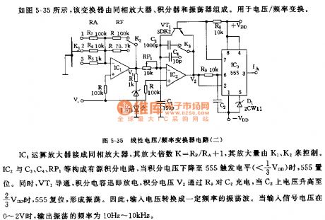
As shown in Figure 5-35, the converter is composed of in-phase amplifier, integrator and oscillator. It is usedfor voltage and frequency conversion. IC1 operational amplifier is connected as an inverting amplifier, the voltage is dropped to the trigger level of 555, 555 sets. At the same time, VT1 is conducted, integration capacitor discharges rapidly, the integrator voltage V2 charges for C2 through R9, when the voltage of C2 rises up to 2/3 VDD, 555 resets, then it forms shocks. Therefore, the input voltage is changed into shock wave with a certain frequency. When the input signal voltage is in the 0 ~ V, the output frequency is 10HZ ~ 10kHz.
(View)
View full Circuit Diagram | Comments | Reading(2842)
| Pages:6/47 1234567891011121314151617181920Under 20 |
Circuit Categories
power supply circuit
Amplifier Circuit
Basic Circuit
LED and Light Circuit
Sensor Circuit
Signal Processing
Electrical Equipment Circuit
Control Circuit
Remote Control Circuit
A/D-D/A Converter Circuit
Audio Circuit
Measuring and Test Circuit
Communication Circuit
Computer-Related Circuit
555 Circuit
Automotive Circuit
Repairing Circuit