
Amplifier Circuit
Index 35
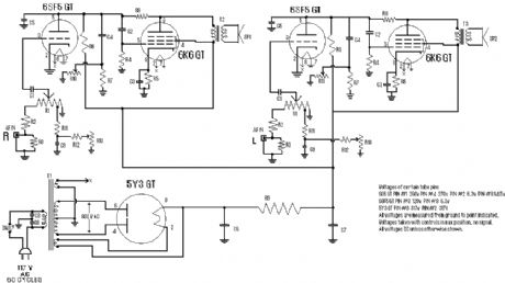
Stereo Tube Amplifier
Published:2012/12/12 0:29:00 Author:muriel | Keyword: Stereo Tube, Amplifier
View full Circuit Diagram | Comments | Reading(825)
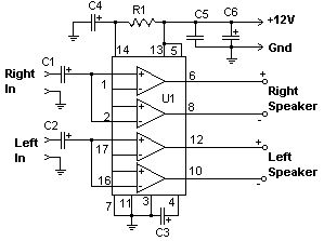
22 Watt Audio Amplifier 1
Published:2012/12/12 0:25:00 Author:muriel | Keyword: 22 Watt , Audio Amplifier
View full Circuit Diagram | Comments | Reading(688)
The pre -stage circuit diagram of 6N7P bravery circuit
Published:2012/12/11 0:52:00 Author:Ecco | Keyword: pre -stage , bravery circuit
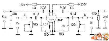
The 6N7P is a common-cathode dual triode with good consistency, and it is used for the push-pull amplifier inverter circuit. This tube has the right characteristics, and it can work at zero gate voltage with mellow sound. In order to appreciate the 6N7P charm, people use 6N7P to form the dual channel pre-stage. And 1.5V battery can be used for gate bias, and the filament is supplied by DC power supply. The 6N7P working point current is 23mA.
(View)
View full Circuit Diagram | Comments | Reading(1289)
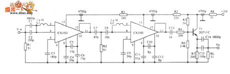
200MHz broadband amplifier circuit diagram with low noise
Published:2012/12/10 0:12:00 Author:Ecco | Keyword: 200MHz, broadband amplifier , low noise
View full Circuit Diagram | Comments | Reading(1000)
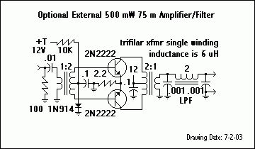
optional external 500mW 75m amplifier/filter
Published:2012/12/6 20:20:00 Author:muriel | Keyword: optional external , 500mW , 75m , amplifier, filter
View full Circuit Diagram | Comments | Reading(985)
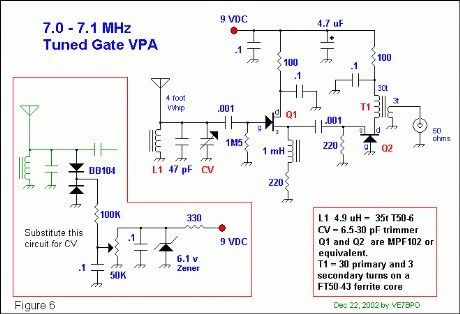
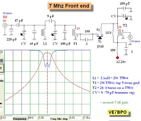
7.0-7.1MHz tuned gate VPA
Published:2012/12/6 20:14:00 Author:muriel | Keyword: 7.0-7.1MHz , tuned gate VPA
View full Circuit Diagram | Comments | Reading(906)
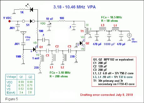
VPA High Pass/Low Pass Filter after Q1 Stage
Published:2012/12/6 20:13:00 Author:muriel | Keyword: VPA , High Pass/Low Pass, Filter, Q1 Stage
View full Circuit Diagram | Comments | Reading(1028)
VPA With A High Pass Filter After The Q1 Stage
Published:2012/12/6 20:13:00 Author:muriel | Keyword: VPA , High Pass Filter, Q1 Stage
View full Circuit Diagram | Comments | Reading(1091)
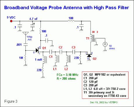
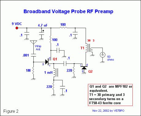
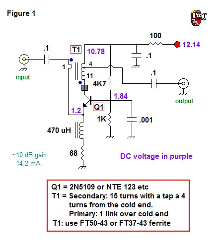
broadband voltage probe RF preamp
Published:2012/12/6 20:12:00 Author:muriel | Keyword: broadband voltage , probe RF preamp
View full Circuit Diagram | Comments | Reading(2241)
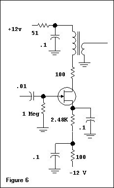
Common source amplifier biased for 5 mA drain current
Published:2012/12/6 20:08:00 Author:muriel | Keyword: Common source amplifier, 5 mA , drain current.
View full Circuit Diagram | Comments | Reading(806)
Resonator
Published:2012/12/6 1:26:00 Author:muriel | Keyword: Resonator
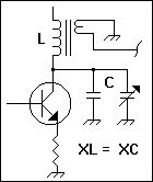
This application calculates the inductor and capacitor values for the tank circuit of a simple bipolar transistor RF amp. The basic schematic is shown above. Enter the center frequency plus the inductive/capacitive reactance you desire and press the Calculate button to calculate the necessary inductance and capacitance for L and C respectively. (View)
View full Circuit Diagram | Comments | Reading(1040)
RF preamp for the 40 Meter band with 3 tuned filters
Published:2012/12/6 1:23:00 Author:muriel | Keyword: RF preamp , 40 Meter band, 3 tuned filters
View full Circuit Diagram | Comments | Reading(1611)
Toroidal Inductor Norton Amp Experiments
Published:2012/12/6 1:23:00 Author:muriel | Keyword: Toroidal Inductor, Norton Amp
View full Circuit Diagram | Comments | Reading(2069)
A Low Noise, High Dynamic Range Broadband RF Amp
Published:2012/12/6 1:22:00 Author:muriel | Keyword: Low Noise, High Dynamic Range, Broadband RF Amp
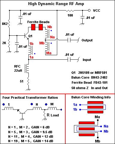
This schematic is a version of a circuit developed and patented by David Norton and Allen Podell in June 1974. This variation was described by Joe Reisert, W1JR in the now defunct Ham Radio Magazine. The Norton design uses transformer coupling to achieve noiseless negative feedback and is really outstanding. A great article utilizing and augmenting on this technique receivers is by Jacob Makhinson, N6NWP in QST magazine for Feb 1993 with A High Dynamic Range MF/HF Receiver Front End . Makhinson arranged 2 in push-pull to obtain excellent results. Obtain a back-issue of QST for closer study. Note that the fore mentioned Feb QST article has the coil phasing wrong and the correct phasing can be seen at this web site from QST for July 1996. There is also information about Norton feedback RF amplifiers in EMFRD.If you are building a contest-grade receiver and need a good RF preamp and/or post mixer amplifier, the Norton type is quite suitable. An amp built using a 2N5109 can have a noise figure in the 2.5 - 3dB range. I have also built them with 2N3866, MRF517, MRF581 and a 2N5179 although the last transistor would be a somewhat poorer choice. This schematic with a 2N5109 is good from 1.8 to 150 MHz with a 1.2:1 VSWR or less according to Joe Reisert. I have even put one in a friends CB radio and he was delighted. (View)
View full Circuit Diagram | Comments | Reading(4070)
VE7GC Popcorn RF Preamp
Published:2012/12/6 1:21:00 Author:muriel | Keyword: VE7GC , Popcorn, RF Preamp
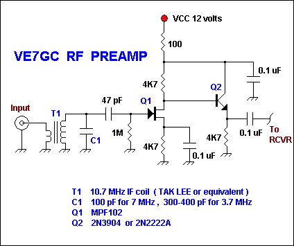
Here is an easy RF preamp by Dick Pattinson, VE7GC. It uses a single tuned circuit at the front end and can connect directly to a mixer or product detector in a simple receiver project. Note how Dick provided adjustable RF gain control for this circuit in his Wee Willy project on this website. If you can not find Tak Lee green 10.7 MHz IF coils, probably any other brand of 10.7 MHz slug tuned IF transformer would work. The Mouser catalog number is 421F123 . If your 10.7 MHz IF coil has a built in capacitor at the base , remove it. A fixed inductor may also be wound using a powdered iron torroid core and then all or a portion of the C1 capacity would be made variable. The input impedance is 50 ohms and the output impedance is low due to the Q2 emitter follower stage.
(View)
View full Circuit Diagram | Comments | Reading(4056)
RF Preamps
Published:2012/12/6 1:21:00 Author:muriel | Keyword: RF Preamps

Here is a schematic sent to me by W1FB many years ago. It is very similar to a 6M two-stage preamp that he published in QST in the mid eighties. Doug really favored the grounded gate FET for narrow band preamps. His published work is replete with examples of them on just about every band. I built that amp and remember getting about 10 dB gain, which is all that I wanted for the 6M direct conversion receiver using a diode ring detector that I was building. The great feature of the amp is that it combines a band pass filter and preamp in one. I lost the original schematic that Doug sent me but was delighted to see that I made a bitmapped drawing of it on a floppy disk that was recently re-discovered when we were moving an old desk. The shield shown in the schematic was a small piece of grounded ,double sided PC board in which, I made a small chamfered hole in to pass the lead going to the T2 tap. The shield, along with very short component leads will help minimize parasitic oscillations. The T2 tap is 3 turns down from the end of the T2 main winding that connects to the variable capacitor. Doug specified T37-10 cores for the inductors, but I substituted T37-6 cores and used the same number of windings as specified for the T37-10 core inductors. It worked fine. (View)
View full Circuit Diagram | Comments | Reading(1154)
Amplifier circuit for low frequency measurement
Published:2012/12/5 21:22:00 Author:Ecco | Keyword: Amplifier, low frequency measurement
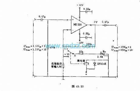
In order to accurately measure small amplitude AC voltage, the measuring circuit with operational amplifier is used. Operational amplifier NE530 can be used, the measurement frequency is more than 200kHz, so it can be used in the low frequency region. Measurement noise voltage can be ignored because it only has a few microvolts. Amplification factor 1 or 10 can be converted by the switch S on negative feedback branch circuit. When the amplification factor is 10, the amplification can be adjusted by potentiometer Rp. For example, if the input voltage is 100mV, you can adjust the output voltage to 1V.
(View)
View full Circuit Diagram | Comments | Reading(2385)
HA-5320 noninverting unit gain mode basic connection circuit
Published:2012/12/5 20:30:00 Author:Ecco | Keyword: noninverting unit, gain mode, basic connection
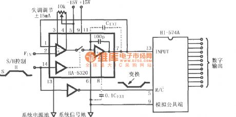
HA-5320 is used as a fast data acquisition A / D converting input stage, the input signal VIN is applied to pin 2 of HA-5320, after being sampling and holding amplified, it is sent to HI574A for analog - digital conversion, then it is converted to 12-bit digital signal output. S non / H signal can control the internal switch's turning on or off, i.e. sampling or holding state. If it needs to extend the hold time, it can be added the external keeping capacitor CEXT.
(View)
View full Circuit Diagram | Comments | Reading(821)
Bench Amplifier
Published:2012/12/3 20:42:00 Author:muriel | Keyword: Bench Amplifier
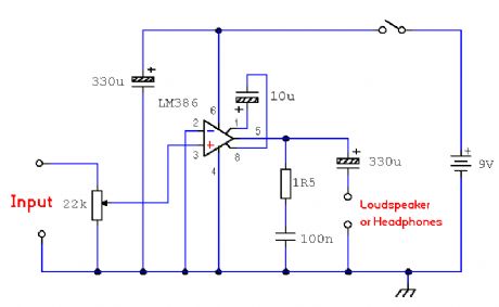
A small 325mW amplifier with a voltage gain of 200 that can be used as a bench amplifier, signal tracer or used to amplify the output from personal radios, etc. (View)
View full Circuit Diagram | Comments | Reading(744)
Three Doorbells For The Hearing Impaired
Published:2012/12/3 20:33:00 Author:muriel | Keyword: Three Doorbells, Hearing Impaired
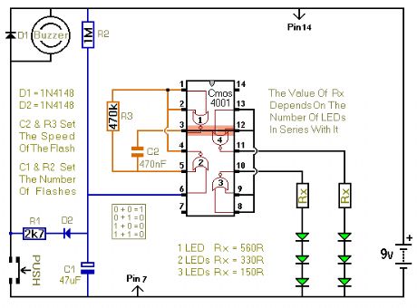
When the push switch is operated - the buzzer will sound and the LEDs will begin to flash. For the hearing members of the household - the buzzer acts as a regular doorbell. It also re-assures the visitor that the doorbell is working. When the push switch is released the buzzer will stop - but the LEDs will continue to flash. The length of time they will go on flashing is set by the values of R2 & C1. With the values shown in the diagram - the LEDs will flash for a further 30 seconds or so. If you make R2 a variable resistor, you can adjust the time period. If you want longer than 30 seconds - increase the value of C1 or R2. (View)
View full Circuit Diagram | Comments | Reading(809)
| Pages:35/250 At 202122232425262728293031323334353637383940Under 20 |
Circuit Categories
power supply circuit
Amplifier Circuit
Basic Circuit
LED and Light Circuit
Sensor Circuit
Signal Processing
Electrical Equipment Circuit
Control Circuit
Remote Control Circuit
A/D-D/A Converter Circuit
Audio Circuit
Measuring and Test Circuit
Communication Circuit
Computer-Related Circuit
555 Circuit
Automotive Circuit
Repairing Circuit