
Amplifier Circuit
Index 20
The Howler Monkey Push Pull 6AQ5 Guitar Amp
Published:2013/3/10 21:57:00 Author:Ecco | Keyword: Howler Monkey , Push Pull , Guitar Amp
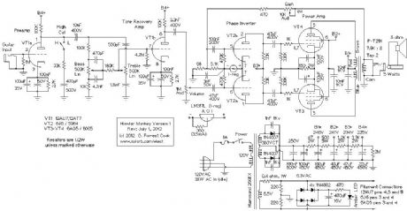
This amplifier is a push-pull design which features a pair of 6AQ5 beam power tubes driven by a 6J6 dual triode, all of which are 7 pin miniature tubes. It is the higher power successor to the the Squirrel Monkey amp project. In fact, the only thing this amp has in common with the Squirrel Monkey amp is the choice of an electrical wiring box for the chassis and a monkey in the name. The 6AQ5 tubes were commonly used as single ended audio output amplifiers in radios and televisions, they are plentiful and inexpensive on the surplus market.
The 6AQ5 output tubes are described in the RCA receiving tube manual as being lower voltage versions of the larger 6V6 beam power pentodes. The maximum undistorted power output from this amplifier is about 5 watts, which is plenty loud for a practice amp. The amp works well driving either a 10 or 12 guitar speaker. A big advantage of the lower power 6AQ5 output tubes is their ability to reach plate starvation, with it's inherently pleasant sounding distortion, at much lower volume levels. This can be an advantage for recording, and for those who wish to preserve their hearing. There are several military versions of the 6AQ5 including the 6005 and the 6094, the latter is a 10K-hour tube with ceramic spacers and thick glass.
The 6J6 dual triode is ideally suited for use as a long-tailed pair phase inverter since the two cathodes are tied together internally. The preamp and tone control recovery amps use a common 12AU7 dual triode, higher gain 12AT7 and 12AX7 tubes can be substituted for the 12AU7 if more gain is desired. The 12AU7 produces a cleaner and softer sound than the higher gain tubes. If one wishes to build the amp entirely with 7 pin tubes, two common 6C4 triodes can be substituted for the 12AU7.
(View)
View full Circuit Diagram | Comments | Reading(5560)
The Squirrel Monkey One Tube Guitar Amp
Published:2013/3/10 21:55:00 Author:Ecco | Keyword: Squirrel Monkey, One Tube , Guitar Amp
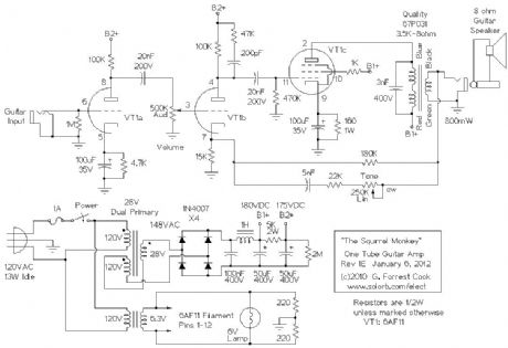
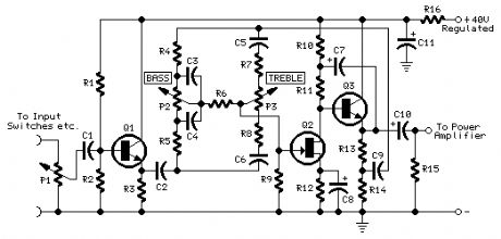
The guitar input jack feeds directly into class-A preamp VT1a, the single high gain triode section in the 6AF11. The preamp output feeds into the volume control pot, and that drives the power amp circuitry, VT1b and VT1c.
VT1b is the first gain stage in the power amp, it includes negative feedback input on the cathode and a high cut R-C network on the plate to lower RF sensitivity. VT1b feeds the output stage, pentode VT1c. Both VT1b and VT1c are running in class-A mode. The pentode is cathode biased to the tube's optimal 24mA by the 160 ohm resistor. The 180K resistor from the transformer output to the VT1b cathode adds a small amount of negative feedback for stabilizing the amplifier. The 3nF capacitor across the output transformer keeps the output stage from oscillating in the RF region.
The tone control is somewhat non-standard, it involves an adjustable high pass network within the power amp's negative feedback loop. The negative feedback inverts this function to make an adjustable high cut filter. The tone control's response is quite useful, musically.
There are a lot of Fender 5E3 fans out there who think that negative feedback is a bad thing in any form. From my experiments, I have found that the secret to using negative feedback is to use a minimal amount. That greatly reduces the production of bad-sounding distortion, while preserving the good-sounding distortion and punchy presence. Bad-sounding distortion is visible on an oscilloscope as very steep waveforms (RF), while good-sounding distortion is visible as the soft rounding of the tops of the waves as a result of plate starvation.
A number of different junk box output transformers were tried in this circuit with minor variations in the performance. A 3.5K to 8 ohm transformer produced the most power output of the transformers that were tested. Since this is a relatively low power amplifier, it is not nececessary for the output transformer to be perfectly matched to the tube, although the volume will be loudest when the match is ideal. Transformers with input impedances from 2.5K to 10K should work and a common 5K to 8 ohm transformer would be a good choice if you cannot locate a 3.5K to 8 ohm unit.
The power supply section uses a standard 6.3VAC/2 Amp filament transformer for lighting the tube filaments up, two 220 ohm resistors cancel out any filament-induced hum.
The high voltage transformer uses a bit of trickery that has been seen elsewhere on Internet amplifier designs. A 28VAC/1 Amp (1/2 Amp would work) transformer with dual primaries is rewired so that one primary winding became a secondary winding and the 28V secondary voltage was added to the 120V secondary to produce 148VAC. This feeds into a bridge rectifier to produce the high voltage DC, which is around 210V with no load. A more common 24VAC dual primary transformer should also work fine here.
The high voltage DC is filtered through a capacitive/inductive pi filter to remove hum and produce the B1+ supply. The B1+ supply runs at around 180VDC with the tube plugged in. The B1+ supply is further filtered through an R/C filter to produce an isolated B2+ supply for the first two gain stages, this runs at around 175V. The 2M resistor discharges the capacitors when power is removed.
(View)
View full Circuit Diagram | Comments | Reading(3487)
FuzzniKator Push-Pull Tube Distortion/Preamp Box
Published:2013/3/10 21:51:00 Author:Ecco | Keyword: FuzzniKator, Push-Pull Tube , Distortion, Preamp Box

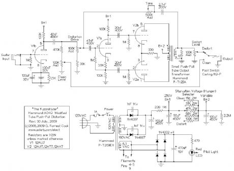
There are zillions of guitar distortion circuits on the Internet, many with funny names. The FuzzniKator is somewhat unique among the lot. The circuit was inspired by the great distortion sound that tube amps give a guitar during the seconds after the power has been shut off and the signal is fading out. The effect is also similar to a cranked tube amp driving a resistive speaker attenuator. The circuit uses a special starved push-pull tube output stage driving an output transformer which drives a resistive load. The push-pull output tubes are run from an adjustable (and lower than normal) B+ voltage in order to starve the tubes and produce distortion. The push-pull configuration and transformer output produce a more harmonically pleasant distortion compared to most diode-clipped distortion effects.
The starvation voltage and drive signal are adjustable for a wide variety of sounds. The FuzzniKator also has a clean tube preamp channel that is similar to a classic Fender amp's tube front-end circuit. The clean channel works nicely as a tube preamp stage and the distortion channel makes any amp, solid state or tube, sound warm and fuzzy.
(View)
View full Circuit Diagram | Comments | Reading(2923)
Hammond AO-44 Reverb Amp to Hi-Fi Amp Conversion
Published:2013/3/10 21:43:00 Author:Ecco | Keyword: Hammond , Reverb Amp , Hi-Fi Amp Conversion
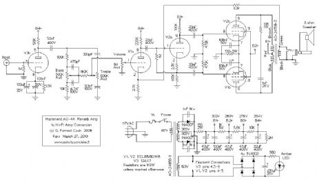
The Hammond AO-44 reverb amplifier was designed to be used an a secondary reverb channel amp in Hammond A-100 and M-series organs. These units can easily be converted into a mono tube amplifier that is suitable for use as one channel in a stereo amp, aka a Mono Block amp. The audio power output is around 8 watts. This project makes a good introduction to working with tubes.
The AO-44 chassis can also be turned into a higher power guitar amplifier using a pair of 6BQ5 pentodes and a 6U10 compactron, see the Spartacus Amp project for details. The Spartacus project is more involved, it requires replacing most of the AO-44 circuitry. The AO-44 amps are currently available for reasonable prices on eBay.
(View)
View full Circuit Diagram | Comments | Reading(3193)
Precision op amp zero circuit
Published:2013/3/1 2:33:00 Author:Ecco | Keyword: Precision, op amp, zero circuit
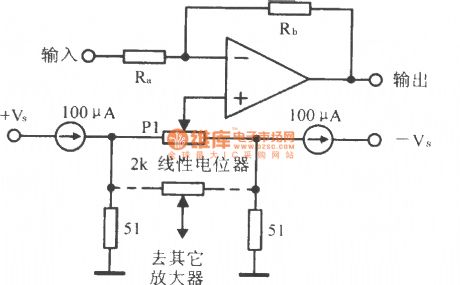
Precision op amp zero circuit is shown as figure.
(View)
View full Circuit Diagram | Comments | Reading(1257)
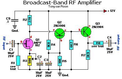
Broadcast-Band RF Amplifier
Published:2013/2/27 20:34:00 Author:muriel | Keyword: Broadcast-Band , RF Amplifier
View full Circuit Diagram | Comments | Reading(0)
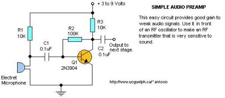
Audio Pre-Amplifier #1
Published:2013/2/27 20:21:00 Author:muriel | Keyword: Audio Pre-Amplifier
View full Circuit Diagram | Comments | Reading(1184)
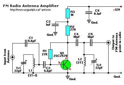
Active FM Antenna Amplifier
Published:2013/2/27 20:15:00 Author:muriel | Keyword: Active , FM Antenna , Amplifier
View full Circuit Diagram | Comments | Reading(1350)
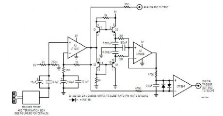
Trigger Probe Amplifier
Published:2013/2/25 20:09:00 Author:muriel | Keyword: Trigger Probe Amplifier
View full Circuit Diagram | Comments | Reading(1270)
Power Ampifier/Current Source
Published:2013/2/25 19:55:00 Author:muriel | Keyword: Power Ampifier, Current Source

View full Circuit Diagram | Comments | Reading(1078)
CATV Amplifiers
Published:2013/2/24 21:19:00 Author:muriel | Keyword: CATV Amplifiers
View full Circuit Diagram | Comments | Reading(1321)
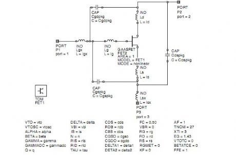
NonLinear HJ-FET Model Verification in a PCS Amplifier 2
Published:2013/2/24 21:06:00 Author:muriel | Keyword: NonLinear HJ-FET Model, PCS Amplifier
View full Circuit Diagram | Comments | Reading(1050)
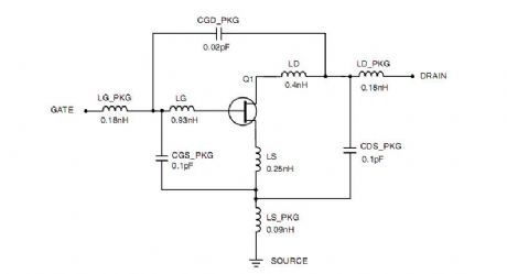
NonLinear HJ-FET Model Verification in a PCS Amplifier
Published:2013/2/24 21:05:00 Author:muriel | Keyword: NonLinear , HJ-FET Model , Verification , PCS Amplifier
View full Circuit Diagram | Comments | Reading(1094)
Class-A Audio Amplifier
Published:2013/2/24 20:59:00 Author:muriel | Keyword: Class-A, Audio Amplifier
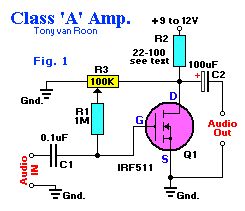
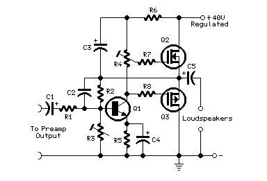
Class-A Audio Amplifier. With zero gate bias applied, Q1 is like switch in the off state, so no current flows through the load resistor R2. Ideally speaking, the voltage across Q1 and the load resistor should be equal for class-A operation. A 100K potentiometer (R3) and a 1-MegaOhm fixed resistor (R1) maker up a simple adjustable gate-bias circuit. Plase a voltmeter between the Drain (D) of Q1 and the circuit ground, and adjust R3 for a meter reading of half the power supply voltage.Almost any resistor value can be used for R2 as long as the maximum current and power ratings of the FET are not exceeded. A resistor value between 22 and 100 ohms is a good choice for experimenting. At high currents, a suitable heat sink should be used. (View)
View full Circuit Diagram | Comments | Reading(4080)
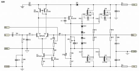
High Power, High Fidelity Lateral MOSFET Power Amplifier 2
Published:2013/2/24 20:57:00 Author:muriel | Keyword: High Power, High Fidelity, Lateral MOSFET , Power Amplifier
View full Circuit Diagram | Comments | Reading(5133)
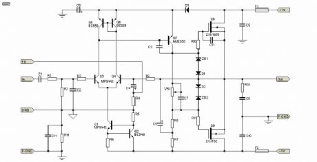
High Power, High Fidelity Lateral MOSFET Power Amplifier
Published:2013/2/24 20:56:00 Author:muriel | Keyword: High Power, High Fidelity, Lateral MOSFET , Power Amplifier
View full Circuit Diagram | Comments | Reading(3566)
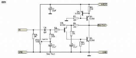
DoZ Preamp as Driver
Published:2013/2/24 20:51:00 Author:muriel | Keyword: DoZ Preamp, Driver
View full Circuit Diagram | Comments | Reading(2824)
Preamps Circuit diagram
Published:2013/2/24 20:49:00 Author:muriel | Keyword: Preamps Circuit
View full Circuit Diagram | Comments | Reading(1646)
Mini-MosFet Audio Amplifiers
Published:2013/2/24 20:48:00 Author:muriel | Keyword: Mini-MosFet, Audio Amplifiers
View full Circuit Diagram | Comments | Reading(2393)
High Power GaAs FET Amplifier 3
Published:2013/2/20 21:04:00 Author:muriel | Keyword: High Power, GaAs FET Amplifier
View full Circuit Diagram | Comments | Reading(988)
| Pages:20/250 1234567891011121314151617181920Under 20 |
Circuit Categories
power supply circuit
Amplifier Circuit
Basic Circuit
LED and Light Circuit
Sensor Circuit
Signal Processing
Electrical Equipment Circuit
Control Circuit
Remote Control Circuit
A/D-D/A Converter Circuit
Audio Circuit
Measuring and Test Circuit
Communication Circuit
Computer-Related Circuit
555 Circuit
Automotive Circuit
Repairing Circuit