
Amplifier Circuit
Index 18
4 Watt / 900Mhz RF Amplifier
Published:2013/3/13 1:01:00 Author:Ecco | Keyword: 4 Watt , 900Mhz , RF Amplifier
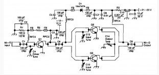
This RF amplifier circuit has a power output of 4 Watts at a frequency of 900 Mhz. Applying Wilkinson power dividers in the base and collector circuits of Q2 and Q3, a couple of SD1853 driver application transistor are paralleled for double the power output of the 2-W amplifier.
(View)
View full Circuit Diagram | Comments | Reading(1843)
1500 Watt RF Amplifier Circuit
Published:2013/3/13 0:59:00 Author:Ecco | Keyword: 1500 Watt, RF Amplifier
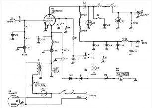
This 1500 watt RF amplifier circuit can be used to drive your transmitter antenna, it can also include driving to the source of the RF high power, microwave heating, and draw the structure of the resonant cavity.
(View)
View full Circuit Diagram | Comments | Reading(1503)
General Purpose 5 Watt Audio Amplifier based LA4460
Published:2013/3/12 1:42:00 Author:Ecco | Keyword: General Purpose , 5 Watt, Audio Amplifier
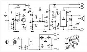
The 5 Watt audio amplifier shown here are suitable for driving the speaker size 8 to 12 inch. Here used an audio output from Sanyo LA4460 IC. The IC is actually used for car radio or car audio power amplifier and may deliver output power up to 12 W. But in this circuit is only used 5W.
The 5 W audio amplifier circuit consists of loudness control, driver amplifier Q1, and the bass and treble controls of approximately ± 10 dB boost / cut. Either the ac supply shown in here can be used, or a 12 Vdc supply can be connected to points A&B (positive) and C (negative). Two of these circuits, using ganged potentiometers at R2, R7, and R11 can be used for stereo applications. T1 is a 12Volt 1 ampere plug-in transformer. Notice that IC1 must be heatsinked. Power output is about 5 W. A 4″ x 2″ x 0.050″ aluminum heatsink should be adequate.
(View)
View full Circuit Diagram | Comments | Reading(1282)
Preamplifier for magnetic phono cartridges
Published:2013/3/12 1:38:00 Author:Ecco | Keyword: Preamplifier , magnetic phono cartridges
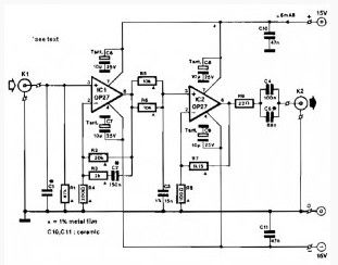
This amplifier circuit is intended to be added to the preamplifier which does not have a phono input. Such a phono input is required for normal record players with a dynamic pick-up, of which millions are still around. Moreover, the amplifier does not only bring the output of the pick-up to line level, it also adds the correction to the frequency response (according to RIAA requirements).
When recording gramophone records, the frequency characteristic is lifted at the high end. This lift must be countered in the playback (pre)amplifier. The corrections to the frequency response characteristic are according to a norm set by the Record Industries Association of America (RIAA) and also by the IEC.
The corrective curve provided by the amplifier is shown in the graph (bold line). The thin line shows the ideal corrective curve. The sharp bends in this at 50 and 500 Hz are nearly obtained in the practical curve by network R3/C2; just above 2 kHz is approached in practice by filter R5/R6/C3. The arrangement of R3/C2 in the feedback loop of IC1 gives noticeably better results than the usual (passive) filter approach.
(View)
View full Circuit Diagram | Comments | Reading(0)
30 watt audio amplifier based TDA2040
Published:2013/3/12 1:37:00 Author:Ecco | Keyword: 30 watt , audio amplifier
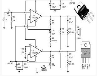
A 30 watt audio amplifier circuit using TDA2040 are shown here. TDA2040 is class AB monolithic integrated audio amplifier available in the package Pentawatt. The IC has a low harmonic distortion and has a built in circuit protection for short circuit.
In the circuit, two TDA2040 ICs are wired in BTL (bridge-tied load) configuration to provide 30W of output into 8 ohm speakers at + /-16V DC. The capacitor C1 is the decoupling capacitor DC input. Network with components R2, C4, R3 provides feedback for IC1 while R7, C6, R8 network provides information for IC2. Network C5, R5 and C9, R9 provides stability at high frequency. Capacitors C2, C3 filters the positive supply rail while the capacitors C7, C8 filters the negative supply rail.
(View)
View full Circuit Diagram | Comments | Reading(3872)
6 Watt HI FI audio amplifier based TDA2613
Published:2013/3/12 1:36:00 Author:Ecco | Keyword: 6 Watt , HI FI , audio amplifier
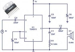
The 6 watt audio amplifier circuit using TDA2613 are shown here. TDA2613 is a Hi-Fi integrated audio amplifier IC from Philips Semiconductors. The IC is ON / OFF button click proof, short circuit, thermal protection and are available only in the 9-pin plastic package inline.
In the above circuit, TDA2613 is wired to operate from a single supply. The capacitor C4 is a DC input coupler while the capacitors C5, C6 are power supply filters. Audio input is fed to the noninverting input through capacitor C4. Inverting input and Vp / 2 pins of the IC are tied together and grounded by the capacitor C3. Capacitor C2 couples the speaker to the output IC and network comprising capacitors C1 and resistor R1 increases stability at high frequency.
(View)
View full Circuit Diagram | Comments | Reading(1445)
Pre Amplifier with low impedance input
Published:2013/3/12 1:34:00 Author:Ecco | Keyword: Pre Amplifier , low impedance input
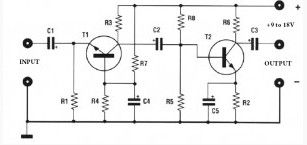
Preamplifier circuit diagram shown here has a low impedance input characteristics, therefore is suitable for use with magnetic transducers: dynamic microphones, low-impedance magnetic heads, sensors phone.
Amplification of this low impedance input pre amp is therefore very high, whether to reduce, there should be a trimmer R3 series to 100 ohms. The system can be powered by a voltage of between 9 and 18Volts. for its realization, follow the diagram layout.
(View)
View full Circuit Diagram | Comments | Reading(2032)
Car stereo amplifier based TDA1535
Published:2013/3/12 1:33:00 Author:Ecco | Keyword: Car stereo amplifier
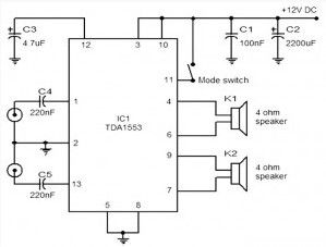
The scheme given here is a car stereo amplifier circuit can be used in That car or other vehicle. The circuitis basedTDA1553,which is aClass-Baudioamplifier. Asyou can seethis circuitisverysimple,consisting onlyof theICand thecapacitor6.
Description:Here is a circuit diagram of car stereo amplifier based on TDA1553. TDA1553 is a monolithic Class B audio amplifier containing two x 22 watt amplifier configuration bridge loads. This amplifier operates from 12V DC and was developed for applications intentionaly car audio. IC also has loads of good features Such as short circuit protection, protection reload, reverse polarity, speaker protection, etc
In the circuit, C4 and C5 are input decoupling capacitor C3 set the time as speaker protection delay. Capacitors C1 and C2 are the feedback filter.
(View)
View full Circuit Diagram | Comments | Reading(1871)
30W Stereo power amplifier based TDA 1521
Published:2013/3/12 1:32:00 Author:Ecco | Keyword: 30W , Stereo power amplifier
It is smallandcompactstereoamplifierispowerfulbutcan easily be usedtoreplaceyourbrokenamplifier ornew construction,ortomakean activespeaker,in all casescombined with a preamplifier. Withremarkable featuresmakeitthe trueHi-Fiamplifier.
Usingonlyactivecomponent(the right andleft channel)PhilipsTDA1521monolithic integratedcircuit,whichcontains adoubleline-endaudioamplifier completely independent,each capable ofprovidingfrom10 to12 Wtothe load8 ohmor15 Winto 4ohms(30Wmusic). Voltagegainsof theamplifierisfixedat 30dB.
(View)
View full Circuit Diagram | Comments | Reading(3125)
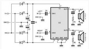
36 Watt Audio Power Amplifier based on TDA1562Q
Published:2013/3/12 1:31:00 Author:Ecco | Keyword: 36 Watt, Audio Power Amplifier
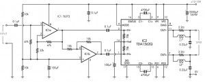

The amplifierbased on theclassHfromPhilipsaudioamplifierIC,itcandeliver36WRMS and 70Wpower music,allfromthe supplyvoltage of13.8V. Thisamplifiercanprovide36WRMScontinuousinto4ohmloadwhen using a13.8Vsupply.
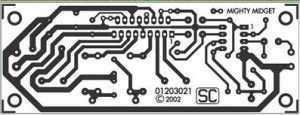
However,itisable todeliver70Woutputpowersignal(music)inthe dynamiccondition. As we cansee fromthe drawingsand schematic diagrams,thispowerfulamplifieruses onlyfewpart.
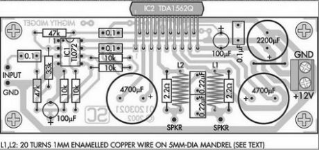
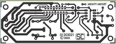
As we cansee fromthe schematicdrawingsanddiagrams,thispowerfulamplifieruses onlyfewpart. It is builton aPCBsize104mmx39mm,buteven thoughits sizemay be simple,butnot withhis ability.Thisamplifieralsohas excellentnoise anddistortion. An importantcomponentsof the circuit isan integratedcircuitTDA1562Q”monolithic integratedBridgeTiedLoad (BTL)classHpower amplifierwithhighefficiency.”Formin17-pinpackage “DIL-bent-SIL”plasticandnotonlydesignedfor use incaraudio amplifier and portablePAbut it worksfor network applications,for example,mini/midiaudio componentsandforTV sound.
PCB :
Technicalfeature:Output power36WRMS:———————-4R70Wmusic power:—————————– 4RFrequency response:28Hztolow———–1dBand 55kHz130mVinput sensitivity:——————— RMS(36Wfor4-ohm)Harmonic distortion:————————– typically0.2% (see charts)SNR95dBunweighted:————————(22Hz to22kHz)
(View)
View full Circuit Diagram | Comments | Reading(4065)
10W MOSFET audio amplifier circuit
Published:2013/3/12 1:28:00 Author:Ecco | Keyword: 10W, MOSFET, audio amplifier
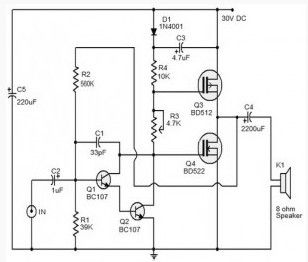
The schemepresented hereis aMOSFET10Waudioamplifier circuitwhichrequires only single power supply. Singlerailsupply is rarely used inClass-Bpower amplifiers. Anyway, it’sgoodenough forlowpower applications. In fact,this circuit is takenfromoldcassette playerthat still works.
PowerMOSFETBD522andBD512is nowobsolete, so you canuseother powerMOSFETaccording toitscharacteristics. Q1andQ2arewiredas apairDarlingtontransistorthat serves as apreamplifier. R3Presetcontrols thequiescent currentwhileR2providing feedback.The outputcoupled to the speakerthroughcapacitorC4.capacitorC5Is apowerfilterandC2isdecouplingcapacitorforDCinput.
(View)
View full Circuit Diagram | Comments | Reading(3266)
Two way 20 watts audio amplifier
Published:2013/3/12 1:27:00 Author:Ecco | Keyword: Two way , 20 watts, audio amplifier
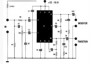
This is a20 watts audio amplifieris suppliedwith a voltage14.4volts,givinga total power of20wattsinto twodifferent channels, each of whichis connectedto thetweeteranda woofer. This amplifier isthereforeequipped with an active CROSSOVERfilterwithacrossoverfrequencyof 2KHz. Eachloudspeakermust supporta power of 10wattsandhaveanimpedanceof 4 ohms.
The supply voltagecan bebetween12and up to 15volts. This two way amplifiercan also bebeneficially usedas aBOOSTERfor2 wayradio.In this case, it is necessaryto place a3.3Kohmresistorbetween theoutputof theradioandthe amplifierinput(seediagram). Toavoid unpleasantdistortion,we mustavoidto applyinputsignalsgreater than 50 mV.
(View)
View full Circuit Diagram | Comments | Reading(1340)
20w car audio amplifier based TDA 2004
Published:2013/3/12 1:25:00 Author:Ecco | Keyword: 20w , car, audio amplifier
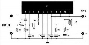
This 20w car audio amplifier circuit described hereoffers a20 wattboosterthatwillallow youtorealize thepower amplifierwith which one canincrease the poweroutputfromthe carstereoup to20Wattsmaximum.
The inputINis connected to theoutputof thereceiver,Uoutputis connectedto the speakeras shownoncaraudioamplifierscheme. It is veryimportanttoensurethat thespeakerhas no connection tothe chassis(ground)ifnot,the integrated circuitIC1,aTDA2004will soon bedamaged. Formounting,carefully followthe implementationof the caraudio amplifier scheme for thecomponents.The power supplywillkeep with 12volts.
(View)
View full Circuit Diagram | Comments | Reading(4946)
15 W class B audio amplifier circuit
Published:2013/3/12 1:24:00 Author:Ecco | Keyword: 15 W , class B , audio amplifier
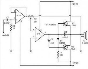
The 15 W class B audio amplifier circuit shown here is a simple class B audio amplifier based onLM833 op amp, TIP41 and TIP42 transistors. LM833 is a dual operational amplifier with high scanning speed and low distortion designed specifically for audio applications. This audio amplifier circuit can provide 15 watts of audio output to a 8-12 ohm speaker with a supply voltage of + /-12V DC dual power.
Dual operational amplifier in the LM833 IC is used here. IC1a is wired as a buffer and C3 works as input decoupling capacitor DC. IC1b is wired inverter mode and it provides a negative feedback. Complementary power transistors TIP41 and TIP42 are wired in Class B push pull system and they drive the speaker. Diode D1 provides a bias voltage of 0.7 V in pair of push-pull and capacitors C2 protect 0.7 V bias voltage through D1 from heavy surge voltage at the output of IC1b.
(View)
View full Circuit Diagram | Comments | Reading(3862)
40W audio amplifier based on TDA1514
Published:2013/3/12 1:23:00 Author:Ecco | Keyword: 40W , audio amplifier
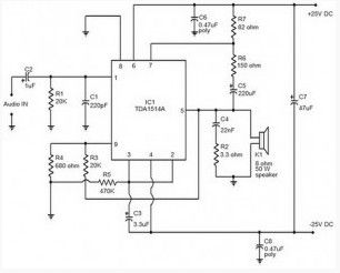
Many electronic audio amplifier circuit has been published here. This time, we use the TDA 1514 high performance hi-fi amplifier from Philips.The IC has many useful features such as thermal protection, Mute / stand-by facilities, low harmonic distortion, etc. This amplifier operates from dual power supply +25 / -25 V DC and can deliver output power of 40Watts into an 8 ohm speaker.
Amplifiedaudiosignalisis given topin1 ofThe ICand thecapacitorC2acts as a DC-coupling.ResistorsR3andR4determine theclosed loop gainandcan varybetween 20and 64dB.ResistorR2andcapacitorC4providesthecorrectimpedancespeaker Zobelnetworkandimprovefrequency response. ResistorsR7, R6and capacitorC5are bootstrapcomponents. Ifthebootstrappingis not requiredthenthese componentscan beremovedandPIN7 can be connected topin6,butpoweroutput will bereduced by about10%.R1isthe input resistanceandbiasthathas an effect oninputimpedance.
(View)
View full Circuit Diagram | Comments | Reading(1650)
Hi Fi headset Amplifier based LM 4880
Published:2013/3/12 1:21:00 Author:Ecco | Keyword: Hi Fi , headset Amplifier
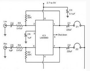
LM4880is adualaudioHiFiamplifierICfromNationalSemiconductor. This headphone amplifier circuitis specificallydesignedtoproducehigh qualityaudiooutputwith aminimum amountof components.LM4880integratedcircuitcapable of delivering250mWper channelinto8ohmload.
IChas aTHDof 0.1%andhas avoltage range of2.7Vto5VDC. In thecircuit shownabove,the resistorsR1andR2arethe feedbackresistor.C4andC5areDCinputdecouplingcapacitor.FilteringcapacitorC3providepowerand reducenoise.The amplifierautomatically shuts offwhena lowlogiclevelis givento the shutdownpin(pin5). The capacitorC6isworkingathalf-supplyfiltering.
(View)
View full Circuit Diagram | Comments | Reading(2201)
50 watt Mosfet amplifier
Published:2013/3/12 1:20:00 Author:Ecco | Keyword: 50 watt, Mosfet amplifier
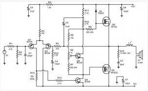
The first stage of the 50 watt Mosfet amplifier is a differential amplifier based on transistors Q1 and Q2. Capacitor C8 is the DC input decoupling, C1 R1 limits input current and a capacitor bypasses undesirable high frequencies. The second stage is composed of the pilot phase transistors Q3 and Q4. The output stage is a complementary push-pull stage based on MOSFET IRF9530 and IRF530.
(View)
View full Circuit Diagram | Comments | Reading(5811)
10W Amplifier for portable cd players
Published:2013/3/12 1:19:00 Author:Ecco | Keyword: 10W Amplifier , portable cd players
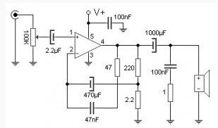
This 10W Amplifier is ideal to drive medium size speakers and use it for a portable CD player or mp3 player. With only one active component of TDA2003 integrated circuit and a single supply source of 8 to 18 volts, this amplifier circuit can provide up to 10W of power to the load which can be between 2 and 8 ohm.
(View)
View full Circuit Diagram | Comments | Reading(1752)
30W, 4 channel car amplifier
Published:2013/3/12 1:18:00 Author:Ecco | Keyword: 30W, 4 channel , car amplifier
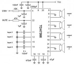
This 4 channel car amplifier comprises only with a single TDA7386 integrated circuit and a few additional components, four independent amplifier channels to build a true multi-channel audio system. Based on the chip was originally designed for car audio, but this amplifier is also ideal for computers with a sound card as the SoundBlaster Live! Creative Labs Inc or Diamond Multimedia Monster Sound / S3.
As seen in the design, the only active component is an integrated circuit TDA7386, SGS-Thomson. It provides four channels of amplification from a 12v source. The DC input is blocked from 0.1μF capacitor. STBY mute control terminal and may or may not be implemented, is up to you. Output is symmetrical, so there is no speaker terminal is grounded (both amplified).
(View)
View full Circuit Diagram | Comments | Reading(2201)
Quad amplifier 40W
Published:2013/3/12 1:17:00 Author:Ecco | Keyword: Quad amplifier , 40W

This circuitprovidesa total of fourspeakers4 ohmsand40Wat12vpowered.It is thereforeidealfor usein the car.Totalharmonic distortionis rather high,about 10%at full power.Butwithhalf the powerrequirements(20W)is lessthan 2%.Anyway itis not intendedtohave ahigh performancesystemin the car.
With theintegratedaudioTDA8571Jdesignedforautomotive applications,this 40w amplifier circuit can expandthe soundof the car radioorconnecta portableMP3playerin it.Internally, thechiphas eightoperationalamplifierseton the bridge, allowingeachspeaker terminalbeing energized.Dontconnect thenegative terminal ofthe mass ofthe speaker,becausetheywillproducea short circuiton theoutput.
(View)
View full Circuit Diagram | Comments | Reading(1613)
| Pages:18/250 1234567891011121314151617181920Under 20 |
Circuit Categories
power supply circuit
Amplifier Circuit
Basic Circuit
LED and Light Circuit
Sensor Circuit
Signal Processing
Electrical Equipment Circuit
Control Circuit
Remote Control Circuit
A/D-D/A Converter Circuit
Audio Circuit
Measuring and Test Circuit
Communication Circuit
Computer-Related Circuit
555 Circuit
Automotive Circuit
Repairing Circuit