
Amplifier Circuit
Index 9
LM3886 60 Watt Amplifier
Published:2013/4/26 1:19:00 Author:muriel | Keyword: LM3886, 60 Watt, Amplifier
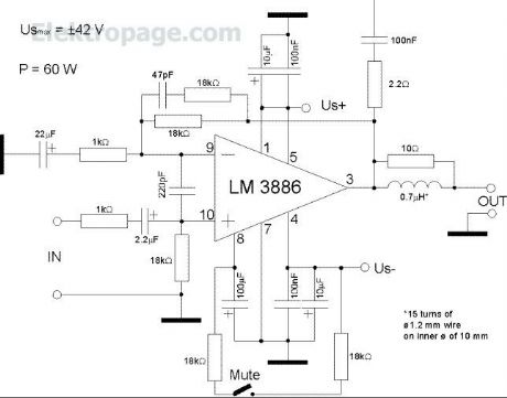

This is one of the stronger amps. It supports stand-by and mute modes. The schematic is rather complicated, because there are some additional devices in the feedback and there are filters both on the input and on the output. (View)
View full Circuit Diagram | Comments | Reading(2768)
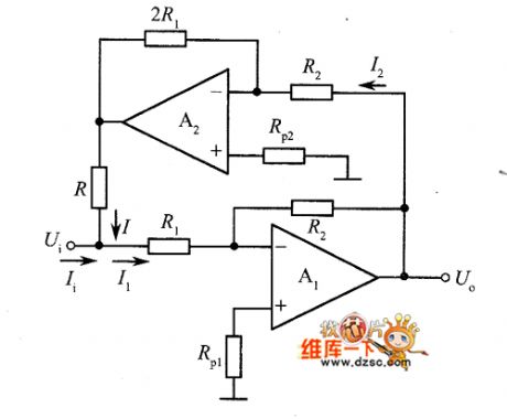
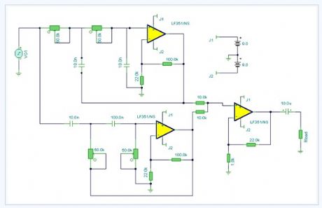
The non-inverting amplifier summing inverter circuit diagram
Published:2013/4/11 1:42:00 Author:Ecco | Keyword: non-inverting amplifier, summing inverter

The non-inverting amplifier summing inverter circuit diagram is shown as figure.
(View)
View full Circuit Diagram | Comments | Reading(1324)
Inverting amplifier circuit diagram using bootstrap circuit
Published:2013/4/11 1:47:00 Author:Ecco | Keyword: Inverting amplifier , bootstrap circuit
Inverting amplifier circuit diagram using bootstrap circuit is shown as figure.
(View)
View full Circuit Diagram | Comments | Reading(1275)
The inverting amplifier circuit diagram with T- resistor network replacing R2
Published:2013/4/11 1:48:00 Author:Ecco | Keyword: inverting amplifier, T- resistor network, replacing R2
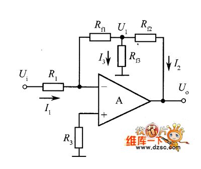
The inverting amplifier circuit diagram with T- resistor network replacing R2 is shown as figure.
(View)
View full Circuit Diagram | Comments | Reading(2562)
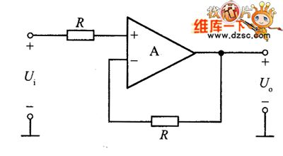
Basic non-inverting amplifier circuit diagram
Published:2013/4/11 1:35:00 Author:Ecco | Keyword: Basic non-inverting amplifier
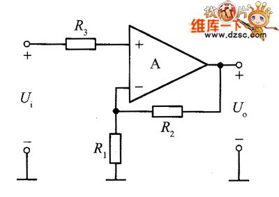
Basic non-inverting amplifier circuit diagram is shown as figure.
(View)
View full Circuit Diagram | Comments | Reading(1228)
Non-inverting amplifier noninverting follower circuit diagram
Published:2013/4/11 1:39:00 Author:Ecco | Keyword: Non-inverting amplifier, noninverting follower
Non-inverting amplifier noninverting follower circuit diagram is shown as figure.
(View)
View full Circuit Diagram | Comments | Reading(1048)
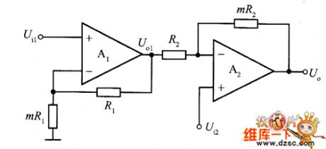
The differential amplifier circuit diagram with adjustable gain
Published:2013/4/11 1:37:00 Author:Ecco | Keyword: differential amplifier , adjustable gain
The differential amplifier circuit diagram with adjustable gain is shown as figure.
(View)
View full Circuit Diagram | Comments | Reading(1880)
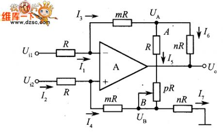
High input impedance differential amplifier circuit diagram
Published:2013/4/11 1:35:00 Author:Ecco | Keyword: High input impedance , differential amplifier
High input impedance differential amplifier circuit diagram is shown as figure.
(View)
View full Circuit Diagram | Comments | Reading(1819)
Integrated instrumentation amplifier circuit diagram
Published:2013/4/11 1:33:00 Author:Ecco | Keyword: Integrated instrumentation amplifier

Integrated instrumentation amplifier circuit diagram is shown as figure.
(View)
View full Circuit Diagram | Comments | Reading(1258)
The amplifier circuit with digital circuit
Published:2013/4/6 22:35:00 Author:Ecco | Keyword: amplifier circuit , digital circuit
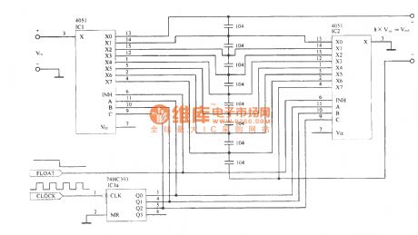
The amplifier circuit with digital circuit is shown as figure.
(View)
View full Circuit Diagram | Comments | Reading(1383)
Mini-box 2w Amplifier electronic circuit
Published:2013/4/1 3:21:00 Author:Ecco | Keyword: Mini-box 2w Amplifier
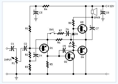
This amplifier was designed to be self-contained in a small loudspeaker box. It can be feed by Walkman, Mini-Disc and CD players, computers and similar devices having line or headphone output. Of course, in most cases you'll have to make two boxes to obtain stereo.The circuit was deliberately designed using no ICs and in a rather old-fashioned manner in order to obtain good harmonic distortion behaviour and to avoid hard to find components. The amplifier(s) can be conveniently supplied by a 12V wall plug-in transformer. Closing SW1 a bass-boost is provided but, at the same time, volume control must be increased to compensate for power loss at higher frequencies.In use, R9 should be carefully adjusted to provide minimal audible signal cross-over distortion consistent with minimal measured quiescent current consumption; a good compromise is to set the quiescent current at about 10-15 mA.To measure this current, wire a DC current meter temporarily in series with the collector of Q3.
(View)
View full Circuit Diagram | Comments | Reading(1815)
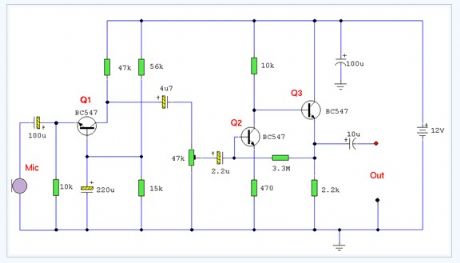
Low Impedance Microphone Amplifier electronic circuit diagram
Published:2013/4/1 3:20:00 Author:Ecco | Keyword: Low Impedance, Microphone Amplifier
The circuit is a microphone amplifier for use with low impedance (~200 ohm) microphones. It will work with stabilized voltages between 6-30VDC. If you don't build the impedance adapter part with T1, you get a micamp for higher impedance microphones. In this case, you should directly connect the signal to C7.
(View)
View full Circuit Diagram | Comments | Reading(1468)
Improved 3 Transistor Audio Amp electronic circuit
Published:2013/4/1 3:17:00 Author:Ecco | Keyword: Improved, 3 Transistor , Audio Amp
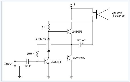
This circuit is similar to the one above but uses positive feedback to get a little more amplitude to the speaker. I copied it from a small 5 transistor radio that uses a 25 ohm speaker. In the circuit above, the load resistor for the driver transistor is tied directly to the + supply. This has a disadvantage in that as the output moves positive, the drop across the 470 ohm resistor decreases which reduces the base current to the top NPN transistor. Thus the output cannot move all the way to the + supply because there wouldn't be any voltage across the 470 resistor and no base current to the NPN transistor. This circuit corrects the problem somewhat and allows a larger voltage swing and probably more output power, but I don't know how much without doing a lot of testing. The output still won't move more than a couple volts using small transistors since the peak current won't be more than 100mA or so into a 25 ohm load. But it's an improvement over the other circuit above. In this circuit, the 1K load resistor is tied to the speaker so that as the output moves negative, the voltage on the 1K resistor is reduced, which aids in turning off the top NPN transistor. When the output moves positive, the charge on the 470uF capacitor aids in turning on the top NPN transistor. The original circuit in the radio used a 300 ohm resistor where the 2 diodes are shown but I changed the resistor to 2 diodes so the amp would operate on lower voltages with less distortion. The transistors shown 2n3053 and 2n2905 are just parts I used for the other circuit above and could be smaller types. Most any small transistors can be used, but they should be capable of 100mA or more current. A 2N3904 or 2N3906 are probably a little small, but would work at low volume. The 2 diodes generate a fairly constant bias voltage as the battery drains and reduces crossover distortion. But you should take care to insure the idle current is around 10 to 20 milliamps with no signal and the output transistors do not get hot under load. The circuit should work with a regular 8 ohm speaker, but the output power may be somewhat less. To optimize the operation, select a resistor where the 100K is shown to set the output voltage at 1/2 the supply voltage (4.5 volts). This resistor might be anything from 50K to 700K depending on the gain of the transistor used where the 3904 is shown.
(View)
View full Circuit Diagram | Comments | Reading(2206)
Headphone Amplifier electronic circuit
Published:2013/4/1 3:16:00 Author:Ecco | Keyword: Headphone Amplifier
View full Circuit Diagram | Comments | Reading(1304)
Guitar Amplifier electronic circuit diagram
Published:2013/4/1 3:16:00 Author:Ecco | Keyword: Guitar Amplifier
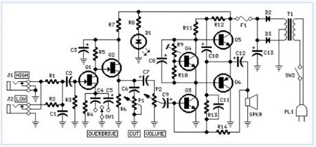
The aim of this design is to reproduce a Combo amplifier of the type very common in the 'sixties and the 'seventies of the past century. It is well suited as a guitar amplifier but it will do a good job with any kind of electronic musical instrument or microphone. 5W power output was a common feature of these widespread devices due to the general adoption of a class A single-tube output stage (see the Vox AC-4 model).Furthermore, nowadays we can do without the old-fashioned Vib-Trem feature frequently included in those designs.The present circuit can deliver 10W of output power when driving an 8 Ohm load, or about 18W @ 4 Ohm.It also features a two-FET preamplifier, two inputs with different sensitivity, a treble-cut control and an optional switch allowing overdrive or powerful treble-enhancement.Technical data are quite impressive for so simple a design:Sensitivity: 30mV input for 10W outputFrequency response: 40 to 20KHz -1dBTotal harmonic distortion @ 1KHz and 10KHz, 8 Ohm load: below 0.05% @ 1W, 0.08% @ 3.5W, 0.15% at the onset of clipping (about 10W).
(View)
View full Circuit Diagram | Comments | Reading(1633)
Ecm Mic Preamplifier electronic circuit
Published:2013/4/1 3:13:00 Author:Ecco | Keyword: Ecm Mic Preamplifier
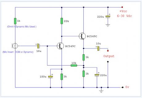
A microphone amplifier that may be used with either Electret Condenser Microphone (ECM) inserts or dynamic inserts, made with discrete components.
(View)
View full Circuit Diagram | Comments | Reading(2007)
Dynamic Microphone Preamp electronic circuit
Published:2013/4/1 3:12:00 Author:Ecco | Keyword: Dynamic Microphone Preamp
View full Circuit Diagram | Comments | Reading(1488)
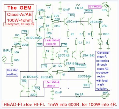
Class-a-ab Amplifier 100w electronic circuit
Published:2013/4/1 3:09:00 Author:Ecco | Keyword: Class-a-ab Amplifier , 100w
View full Circuit Diagram | Comments | Reading(2566)
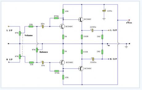
Cheap Audio Booster electronic circuit diagram
Published:2013/4/1 3:08:00 Author:Ecco | Keyword: Cheap Audio Booster
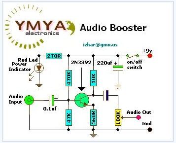
View full Circuit Diagram | Comments | Reading(3827)
Audio Notch Meter electronic circuit diagram
Published:2013/4/1 3:06:00 Author:Ecco | Keyword: Audio Notch Meter
View full Circuit Diagram | Comments | Reading(1109)
| Pages:9/250 1234567891011121314151617181920Under 20 |
Circuit Categories
power supply circuit
Amplifier Circuit
Basic Circuit
LED and Light Circuit
Sensor Circuit
Signal Processing
Electrical Equipment Circuit
Control Circuit
Remote Control Circuit
A/D-D/A Converter Circuit
Audio Circuit
Measuring and Test Circuit
Communication Circuit
Computer-Related Circuit
555 Circuit
Automotive Circuit
Repairing Circuit