
Amplifier Circuit
Index 11
Single Cell Battery Meter Amplifier circuit
Published:2013/3/29 4:37:00 Author:Ecco | Keyword: Single Cell Battery , Meter Amplifier
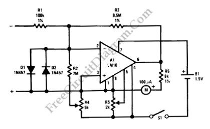
A meter amplifier can be designed using LM10 integrated circuit (IC). The accuracy of full-scale sensitivity is good for over 15°C to 155°C at 10mV and 100nA. Here is the schematic diagram of the circuit:
(View)
View full Circuit Diagram | Comments | Reading(1167)
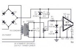
Audio Power Amplifier circuit for AM Radio
Published:2013/3/29 4:27:00 Author:Ecco | Keyword: Audio Power Amplifier, AM Radio
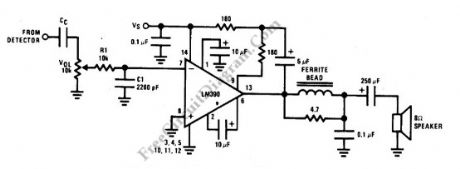
This is an AM radio power amplifier circuit. What is different with other general amplifier is that this circuit has a low-pass filter (passive type), built using R1C1 to limit the input-output frequency response. Additionally, a ferroxcube K5-001-001/3B with 3 turns of wire is used as ferrite bead at output filter. All components should be spaced very close to the IC. The ground and speaker lead must be twisted tightly. The supply lead and supply ground also must be twisted very tightly. Here is the schematic diagram of the circuit:
(View)
View full Circuit Diagram | Comments | Reading(2465)
22W Amplifier circuit for 12V Power Supply Systems
Published:2013/3/28 4:14:00 Author:Ecco | Keyword: 22W Amplifier, 12V Power Supply
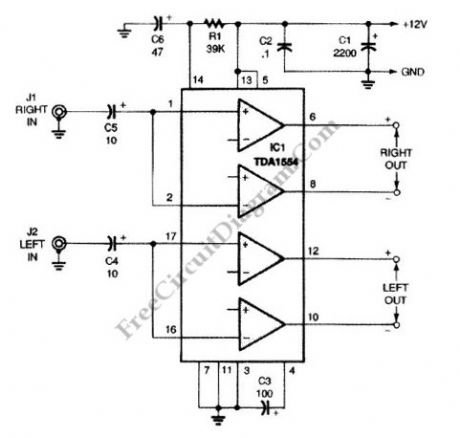
This is a 22-W Amplifier circuit that is designed for or 12-V DC power supply Systems. There are many application for this circuit, such as in car audio application. In car electrical power supply system, the 12V power supply will be provided by the host vehicle’s battery. The capacitor C3 is used to give ripple rejection, since noisy power supply voltage is common in automotive electrical system. The power supply noise signal on car power supply is decoupled by the capacitors C2 and C1. Smaller capacitor C2 is needed to decouple the high frequency noise, since the larger cap (C1) usually has high equivalent series inductance that prevent the high frequency noise (such as glitch or spike) to be bypassed. The capacitors C5 couple the incoming audio signal to IC1 while decoupling static DC offset. For better bass response, this circuit prevent rolling off of the low audio frequencies by choosing a relatively large capacitance for small signal, 10μF capacitors. Here is the schematic diagram of the circuit:
(View)
View full Circuit Diagram | Comments | Reading(1957)
Pre-Amplifier Circuit Diagram for Oscilloscope
Published:2013/3/28 4:09:00 Author:Ecco | Keyword: Pre-Amplifier, Oscilloscope
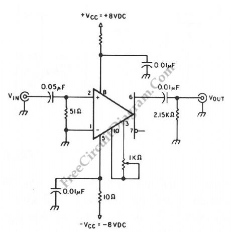
An oscilloscope amplifier with 20 dB voltage gain is provided by this circuit with a frequency range from 0.5 to 50 MHz. By increasing the value of the 0.05 uF capacitor or try removing the capacitor, we can extend the low frequency response of this circuit. A particularly small level of input noise is delivered by this circuit, measured at approximately 20uA over a bandwidth range at 15 MHz. By adjusting the gain potentiometer connected between pins 3 and 10, then adjust the 1-KΩ trimmer potentiometer for an exact voltage gain of 10 are the ways to calibrate the gain. This helps preserve the scale factor of the oscilloscope.
(View)
View full Circuit Diagram | Comments | Reading(2112)
Fast Amplifier Circuit diagram with DC Stabilization
Published:2013/3/28 4:09:00 Author:Ecco | Keyword: Fast Amplifier , DC Stabilization
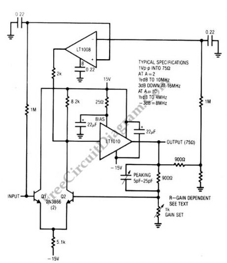
This amplifier circuit combines the LT1010 and a fast discrete stage with an LT1008 based dc stabilizing loop. A differential stage which is single-ends into the LT1010 is formed by Q1 and Q2. An output of 1 V pk-pk into a typical 75-Ω video load is delivered by the circuit. With gain = 2, the gain is considered flat up to 10MHz since it only attenuated about -0.5dB, with the -3 dB point occurring at 16 MHz. At gain = 10, this amplifier flat curve will be up to 4 MHz (0.5dB deviation), with -3 dB point at 8 MHz. The peaking adjustment should be optimized under loaded output conditions. This is a simple stage amplifier for fast applications where relatively low output swing is required. For video amplifier application, 1 V pk-pk output works nicely. A possible problem is the relatively high bias current, typically 10 μA. Additional swing is possible, but more circuitry is needed.
(View)
View full Circuit Diagram | Comments | Reading(1285)
TDA7056 3W BTL Mono Audio Power Amplifier circuit diagram
Published:2013/3/28 4:02:00 Author:Ecco | Keyword: 3W , BTL, Mono , Audio Power Amplifier
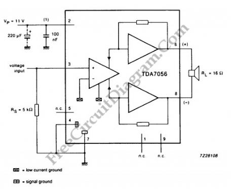
For mono output amplifier application, TDA7056 IC can be your option. Compact but powerful, this integrated circuit is contained in a 9 pin medium power package. This device is designed for battery fed portable equipments such as mono recorders, radios and television. To attract the market, TDA7056 has many features such as low power consumption. For more reliable operation, TDA7056 also has short circuit proof and ESD (Electro Static Discharge) protected on all pins. Designing application with this IC should be easy since no external components is needed. To make sure you’ll love this chip, this device also has no switch on/off clicks. Overall, TDA7056 has good stability.
(View)
View full Circuit Diagram | Comments | Reading(3421)
The instrumentation Amplifier with CMRR Calibration
Published:2013/3/28 3:59:00 Author:Ecco | Keyword: Instrumentation Amplifier , CMRR Calibration
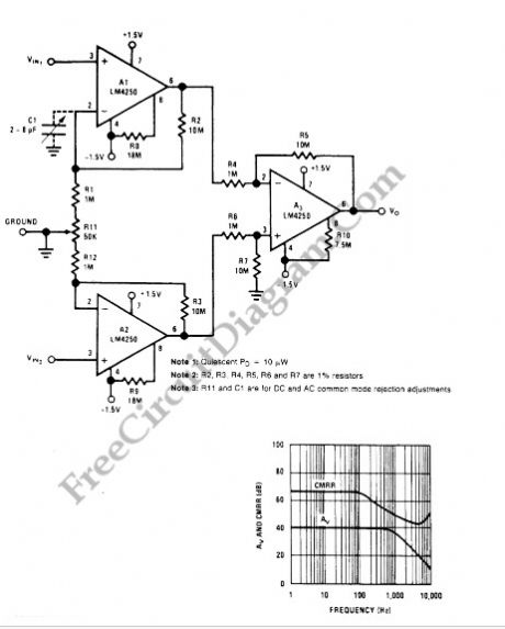
Common mode rejection ratio (CMMR) is one parameter that specify the instrumentation performance. LM4250 is high performance op-amp which is characterized by very low power consumption. With special arrangement as shown in the following schematic diagram, the instrumentation amplifier circuit will be featured with calibration to maximize the CMMR performance.
(View)
View full Circuit Diagram | Comments | Reading(1520)
Voltage Controlled Variable Gain Video Amplifier
Published:2013/3/28 3:43:00 Author:Ecco | Keyword: Voltage Controlled , Variable Gain, Video Amplifier
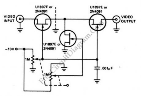
This is a video amplifier circuit featured with controllable variable gain. The control is done by adjusting the voltage of grid inputs of two FETs, which are configured as programmable voltage divider. This circuit can generate dynamic linear range attenuation up to 100 dB. This circuit still give a linear attenuation even at f=10.7MHz. You can see the control is done by a potentiometer, but you can replace with any voltage source ranging from zero to -10V, just make sure each of the two FETs is fed with different synchronized voltages. How to make this two synchronized voltages is described as follow: the first FET is fed with U1, which ranges from 0 to -10 V, and the second FET is controlled by U2, which is synchronized as (-10 – U1) V. This control voltages can be obtained from DAC (digital-to-analog converter) or a stereo potentiometer (as depicted in the diagram). You can see a grounded 0.001 uF capacitor to filter the control voltage from any glitch caused by dirty or bad potentiometer. Here is the schematic diagram of the circuit:
(View)
View full Circuit Diagram | Comments | Reading(0)
Tube Mic Pre-Amp
Published:2013/3/27 3:51:00 Author:Ecco | Keyword: Tube Mic Pre-Amp
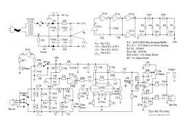
The following diagram is the circuit diagram of tube mic pre amplifier 12AX7. This circuit is little hard to built. You must have an intermediate or advanced skills to build this circuit. All capacitors with value of 33uF are 16V, while the all others are 50V unless marked otherwise. Resistors marked with “#” are 1% metalfilm resistor type.
(View)
View full Circuit Diagram | Comments | Reading(1846)
Tone Booster
Published:2013/3/27 3:49:00 Author:Ecco | Keyword: Tone Booster
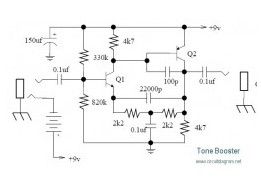
Below circuit is the tone booster circuit. According to the name of circuit, the purpose is to gain the sound signal to become more powerful in both low and high frequencies. Transistor type: Q1 – ztx384 ; Q2 – BC415p The circuit’s peaks frequencies is at 5000 Hz for a cleaner and more penetrating sound.
(View)
View full Circuit Diagram | Comments | Reading(1447)
VOX Treble Booster
Published:2013/3/27 3:47:00 Author:Ecco | Keyword: VOX Treble Booster
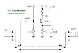
The following diagram is the circuit diagram of VOX Treble Booster. Vox made a variety of boosters that were meant to be plugged directly into amplifiers or guitars. Original VOX Treble Booster diagram:
(View)
View full Circuit Diagram | Comments | Reading(1370)
20W Power Tube Amplifier with EL34
Published:2013/3/27 3:46:00 Author:Ecco | Keyword: 20W , Power Tube, Amplifier
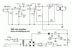
The following diagram is the circuit diagram of 20W power amplifier which build based tube component EL34. EL34 is very famous tube and great for power tube amplifier. The circuit above is complete circuit contains tube amplifier circuit diagram and power supply circuit diagram. To make the stereo channel amplifier, build the similar amplifier circuit only and connect to the power supply using parallel connection with another same amplifier.
(View)
View full Circuit Diagram | Comments | Reading(2179)
Distortion Booster
Published:2013/3/27 3:45:00 Author:Ecco | Keyword: Distortion Booster
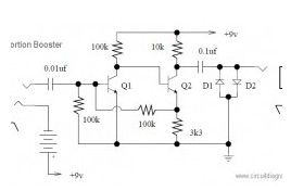
The following circuit is an distortion booster effect for your electric guitar. I don’t know whether this circuit is really works or not, you may try this circuit with your own risk. Circuit notes: Q1 and Q2 are BC108 D1 and D2 are silicon or germanium (pick your favorite flavor) signal diodes.
(View)
View full Circuit Diagram | Comments | Reading(1062)
Guitar Pre-Amp with JFET 2N5457
Published:2013/3/27 3:43:00 Author:Ecco | Keyword: Guitar Pre-Amp , JFET
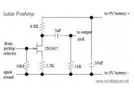
Designed by Don Tillman, this guitar pre-amp circuit design is dedicated for people who don’t like op-amps. This circuit is a discrete JFET pre-amp design, use 2N5457 as the main component. It has low noise, low distortion, low feedback, overloads gracefully, is small, etc.
(View)
View full Circuit Diagram | Comments | Reading(3180)
Simple Mic Pre-Amp based LM358
Published:2013/3/27 3:42:00 Author:Ecco | Keyword: Simple Mic Pre-Amp
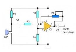
Here the simple audio mic pre amplifier circuit based on single IC LM358. The circuit is very simple, inexpensive and easy to built. Component Parts List: R1, R3, R4 = 10K R2 = 1K R5 = 100K-1M Potensiometer C1 = 0.1uF C2 = 4.7uF/16V IC1 = LM358 dual op-amp single supply Mic = Electret Microphone
(View)
View full Circuit Diagram | Comments | Reading(2700)
Small Audio Booster
Published:2013/3/26 3:43:00 Author:Ecco | Keyword: Audio Booster
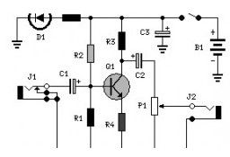
Here the simple, low cost and easy audio booster circuit. It uses a transistor of 2N3392 ad the main amplifier. Component List: R1 = 47K R2 = 470K R3 = 10K R4 = 560R R5 = 270R C1 = 0.1uF/25v C2 = 3.3uF/25v C3 = 470uF/25V P1 = 100K Q1 = 2N3392 D1 = 5mm.
(View)
View full Circuit Diagram | Comments | Reading(1340)
Telephone Amplifier using LM386
Published:2013/3/26 3:39:00 Author:Ecco | Keyword: Telephone Amplifier
The following diagram is the circuit diagram of telephone amplifier, build based small amplifier IC LM386. This is a easy build telephone amplifier There is no extra electrical power supply required to power up the telephone amplifier circuit, as it draws power from the telephone line itself. The amplifier will supply fairly very good volume for the telephone conversation to be effectively heard in a living room.
(View)
View full Circuit Diagram | Comments | Reading(1380)
16W Bridge Amplifier using LM383
Published:2013/3/26 3:38:00 Author:Ecco | Keyword: 16W Bridge Amplifier
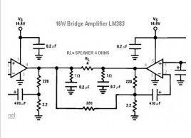
The following diagram is 16W audio amplifier circuit. The circuit built based 2 pieces of power IC LM383 in bridge connection, so this amplifier is an bridge amplifier. This is an old amplifier, LM383 is discontinued, so this LM383 might be difficult to find. You can use ECG1232, TDA2002 or TDA2003 as the replace for LM383.
(View)
View full Circuit Diagram | Comments | Reading(1883)
Transistored 10W Audio Amplifier
Published:2013/3/26 3:36:00 Author:Ecco | Keyword: Transistored , 10W, Audio Amplifier
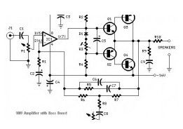
Build based operational amplifier NE5532 and a couple of power transistor TIP41A / TIP42A, this audio amplifier circuit has capability to deliver up to 10W audio power output into 8 ohm speaker.. Amplifier Parts list: P1 22K = Log.Potentiometer P2 = 100K Log.
(View)
View full Circuit Diagram | Comments | Reading(1640)
MOSFET Linear Amplifier 300W/50MHz
Published:2013/3/26 3:36:00 Author:Ecco | Keyword: MOSFET Linear Amplifier, 300W/50MHz
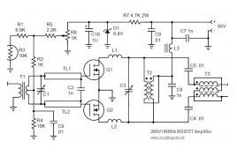
This MOSFET RF Linear Amplifier has capability to deliver up to 300W for 50MHz. The circuit built based the couple of MOSFET ARF448A and ARF448A.
(View)
View full Circuit Diagram | Comments | Reading(4320)
| Pages:11/250 1234567891011121314151617181920Under 20 |
Circuit Categories
power supply circuit
Amplifier Circuit
Basic Circuit
LED and Light Circuit
Sensor Circuit
Signal Processing
Electrical Equipment Circuit
Control Circuit
Remote Control Circuit
A/D-D/A Converter Circuit
Audio Circuit
Measuring and Test Circuit
Communication Circuit
Computer-Related Circuit
555 Circuit
Automotive Circuit
Repairing Circuit