
Amplifier Circuit
Index 17
Small Electret Microphone Pre-amplifier
Published:2013/3/13 2:06:00 Author:Ecco | Keyword: Small Electret, Microphone , Pre-amplifier

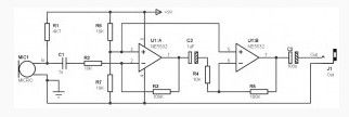
The mic pre amp described here is designed to connect a small electret microphone and uses an integrated circuit type NE5532.
As you can see, this scheme is very simple. The use of a dual operational amplifier type NE5532 is a large part in simplicity, although it was quite possible to simplify even more by using a single transistor.
(View)
View full Circuit Diagram | Comments | Reading(2981)
Low Voltage Bridge Audio Amplifier
Published:2013/3/13 2:05:00 Author:Ecco | Keyword: Low Voltage, Bridge Audio Amplifier
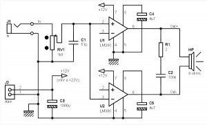
Low voltage bridge audio amplifier based on op amp IC LM386 (Low Voltage Audio Power Amplifier). Application of this circuit include AM-FM radio amplifiers, Portable tape player amplifiers, intercoms, TV sound systems, Line drivers Ultrasonic drivers, Small servo drivers Power converters. This circuit can be operated by battery power.
This Low voltage bridge audio amplifier circuit is for low voltage applications requiring high power outputs. Output power levels of 1.0 W into 4 ohm from 6 V-and 3.5 W into 8 ohm from 12 V are typical. Coupling capacitors are not necessary since the output dc levels will-be within a few tenths of a volt of each other. Where critical matching is required the 500 K potentiometer is added and adjusted for zero dc current flow through the load.
(View)
View full Circuit Diagram | Comments | Reading(2048)
Non-Inverting Amplifier Using Split Supply
Published:2013/3/13 2:04:00 Author:Ecco | Keyword: Non-Inverting Amplifier, Split Supply
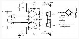
Non-inverting amplifier uses a dual audio power amplifier LM1877 type. This IC can deliver output power of 2 W per channel.
As the title that this circuit requires a dual power supply circuit as shown in the schematic above. This Non-inverting audio amplifier circuit may be applied to Multi-channel audio systems, stereo phonographs, tape recorders and players, AM-FM radio receivers, servo amplifiers, Intercom systems, Automotive products.
(View)
View full Circuit Diagram | Comments | Reading(1069)
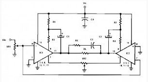
Mono/Stereo Preamp based on LM387
Published:2013/3/13 2:03:00 Author:Ecco | Keyword: Mono/Stereo Preamp
Mono Preamp (or stereo), based on an LM387 for dynamic microphone. The preamplifier described here is designed to connect a small dynamic mic. We will see that it can adapt to a wide range of microphones.
As you can see, Mono Preamp (or stereo), based on an LM387 diagram is very simple. It is based on the use of an LM387, which is really common, but has proven in the field of “low noise”, just like its cousin the LM381.
(View)
View full Circuit Diagram | Comments | Reading(2011)
Mono Preamp based on CMOS IC CD4069
Published:2013/3/13 2:02:00 Author:Ecco | Keyword: Mono Preamp , CMOS IC
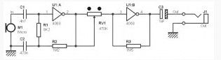
Microphone preamp described here is not a professional preamp, but the original preamp and it is cheap and easy to build. Why the original? Because it does not use non-conventional transistors or operational amplifiers (op amps) to amplify the signal from the microphone, but a set of logic gates are commonly used in digital electronics. Digital ICs used are as in the title above which is cmos CD 4049.
As said above, this scheme there are no transistors or components “analog” to ensure amplification of the signal from the microphone. Except for only two logic gates share the work. Microphones, which are provided to capture the sound,connected to the input of the first logic gate U1: A. This ensures that the amplifier logic gate rate is determined by the value of the resistors R1 and R2. The second logic gate U1: B, in turn, ensures that amplification can be adjusted using potentiometer RV1.
(View)
View full Circuit Diagram | Comments | Reading(1790)
Mono Preamp with Small Transformer and Two Transistors
Published:2013/3/13 2:01:00 Author:Ecco | Keyword: Mono Preamp , Small Transformer , Two Transistors
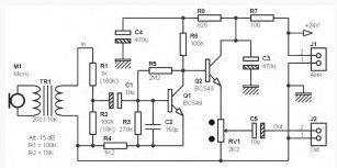
The microphone preamplifier described here is a ‘hybrid’ passive / active. A small transformer input provides a small contribution to the gain of all (about 10 dB), and a transistor provides the additional gain (35 dB) for normal use with a small dynamic microphone. About 40 kHz bandwidth, small and simple installation that requires little space.
(View)
View full Circuit Diagram | Comments | Reading(1390)
5W / 8 Ohms Bridge Amplifier based on Two LM380s
Published:2013/3/13 1:28:00 Author:Ecco | Keyword: 5W , 8 Ohms, Bridge Amplifier
The Audio amplifier described here uses two small amplifiers like LM380 mounted in bridge. Two smallamplifiersLM380(2.5Wmaxineach18V), which mountedbridgemode make it possible togetafew wattsinto 8ohms load.
LM380 mounted on the first non-inverting amplifier, the audio signal connected to + input. The second inverting amplifier mounted on the same audio signal line and connected at the input -. Input (inverting input of U1 and U2 non-inverting input) is not connected to anything. In fact, the internal resistance of 150 Kohm C1 reduces this input to ground. Both amplifiers each have a gain of 34 dB (voltage gain of about 50), the value specified by the manufacturer LM380. With 12 V power supply voltage and input power around 100mV can be generated around 4 W. Power of 5 W is achieved with a supply voltage of 18 V (even with this voltage can reach 6 W without any problems).
(View)
View full Circuit Diagram | Comments | Reading(2028)
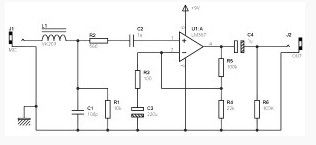
Max 1W / 8 Ohms Amplifier based on LM386 with Input for Guitar
Published:2013/3/13 1:26:00 Author:Ecco | Keyword: Max, 1W , 8 Ohms, Amplifier , Input , Guitar
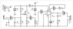
This 1 watt amp is very easy to built in very small dimensions, working with only single 9V battery, and is based on amplifier IC type LM386, its capable to deliver a power for some hundreds milliwatts to 8 ohms load, while consuming only a few mA at rest.
Associated with a small FET input stage, this amplifier is ideal for beginners to make some small electric guitar amplifier. Don’t think you will get results similar to those offered by the amps of a certain class, but for someone who starts in the DIY, and choosing a good size of speaker driver, it’s a nice little montage.
(View)
View full Circuit Diagram | Comments | Reading(1574)
Simple Amplifier Circuit 3W / 8 ohm
Published:2013/3/13 1:25:00 Author:Ecco | Keyword: Simple Amplifier , 3W , 8 ohm
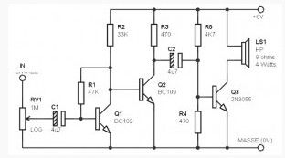
These Simple amplifier based transistor 3W / 8 ohm are very small and very easy to carry, work with single supply between 4V and 9V. It is based on the use of common transistors and is able to provide some low wattage.
(View)
View full Circuit Diagram | Comments | Reading(3328)
35W Audio Amplifier based LM391
Published:2013/3/13 1:20:00 Author:Ecco | Keyword: 35W , Audio Amplifier
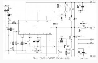
This is the circuit diagram of a 35W audio amplifier based on LM391. The LM391 is a comprehensive driver to the power transistors. It needs only few external components to work. With the TR1 we can adjust the bias current to 45mA. Inductor L1 consists of 20 turns of wire thickness of 0.9mm, around the resistor R16. The transistors Q3-4 must be placed onto a heatsinks. If you use the Q3-4 with type of TIPxxxx, you can be placed directly onto the board. But if you use packaged transistors TO-3, then it should be connected with short cables to the respective positions of the board.
(View)
View full Circuit Diagram | Comments | Reading(1652)
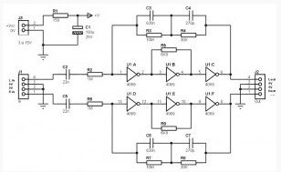
RIAA Stereo Preamplifier Classic Version based on NE5532
Published:2013/3/13 1:19:00 Author:Ecco | Keyword: RIAA , Stereo Preamplifier, Classic Version
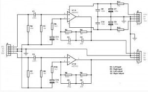
ThisRIAA stereo preamplifier uses only conventional components, you can easily find components at electronics store. The circuit is intended to be used with a vinyl turntable equipped with analog outputs (RCA). It provides the dual function of preamplifier and RIAA correction. This circuit is suitable for a MM (Moving Magnet), and is not suitable for a MC (Moving Coil).
(View)
View full Circuit Diagram | Comments | Reading(1640)
RIAA Stereo Preamplifier Classic Version based on NE5534
Published:2013/3/13 1:17:00 Author:Ecco | Keyword: RIAA , Stereo Preamplifier , Classic Version
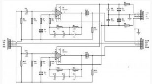
Here the RIAA stereo preamplifier classic version based on NE5534. This setting is intended for use with a vinyl turntable equipped with an analog output (RCA). It provides the dual function of pre-amplification and RIAA correction. This RIAA pre amp circuit is suitable for MM cells (Moving Magnet), and is not suitable for cell MC (Moving Coil). It is slightly more efficient than “RIAA stereo preamplifier classic version, based on the NE5532″.
(View)
View full Circuit Diagram | Comments | Reading(1706)
Simple RIAA Preamplifier using Logic IC CD4069
Published:2013/3/13 1:14:00 Author:Ecco | Keyword: Simple, RIAA Preamplifier, Logic IC
The simple RIAA preamplifier circuit is just to show that we can sometimes change the role of a component. It is possible to use this type of inverting logic gates CD4069 for the read head signal amplification for vinyl turntable. The same thing can be considered for a microphone preamp.
(View)
View full Circuit Diagram | Comments | Reading(2113)
Video Amplifier Circuit based IC LM359
Published:2013/3/13 1:09:00 Author:Ecco | Keyword: Video Amplifier
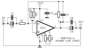
This is the simple and easy to build video amplifier circuit based IC LM359. The LM359 is a Dual, high speed, programmable and Current Mode (Norton) amplifier chip which can be used for general purpose video amplifiers.
(View)
View full Circuit Diagram | Comments | Reading(2049)
Hydrophone Preamplifier based on Op-Amp OPA37
Published:2013/3/13 1:08:00 Author:Ecco | Keyword: Hydrophone Preamplifier
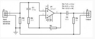
This is Hydrophone preamplifier circuit diagram, designed to be used with a transducer type EDO6166, and is taken from an application note of OPA27/37 of Burr-Brown.
As you can see, it’s really very simple and uses only conventional components. The transducer used, is piezo type and has a relatively high output impedance, which requires a preamp with a high input impedance. The input impedance of this circuit is mainly determined by the value of the resistor R3, 1 MOhms here. The value of other components determines the frequency range used, it ranges here between 1 kHz and 50 kHz.
(View)
View full Circuit Diagram | Comments | Reading(2341)
Amplifier Circuit using MOSFET Output Stage
Published:2013/3/13 1:07:00 Author:Ecco | Keyword: Amplifier, MOSFET Output Stage
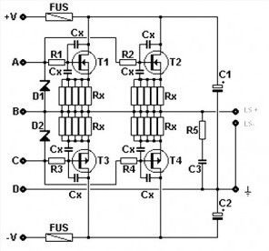
The circuit presented here is amplifier circuit using MOSFET output stages, as a substitute for the output stage based on bipolar transistors. This project is for those who want to experiment with the power MOSFET. Without going into details, the MOSFET has a characteristic sound of vacuum tubes and bipolar transistors. The main advantages MOSFET Amplifier : simplicity of operation, hundreds of watts with a simple parallel, negative temperature coefficient and fast switching times. The main disadvantages : a high input capacity from 500 to 1000 pF, sensitivity to electrostatic discharge.
MOSFETs are available in a very wide range in the PNP and NPN, the voltage from 100 to 200 volts or more, additional models (such as bipolar). Model commonly used in power amplifiers are 10N16, 10P16, IRFP140, IRFP9140, IRFP240, IRFP9240, 2SK135, 2SJ50, 2SK1530, 2SJ201. In this project, points A and C are connected to the output of the driver stage, point B is to counter-reaction and the point D the mass driver. Board is planned for the case TO3P transistors, it will slightly bend the foot for TO220-type packages.
(View)
View full Circuit Diagram | Comments | Reading(2302)
Headphones Amplifier based LM741
Published:2013/3/13 1:06:00 Author:Ecco | Keyword: Headphones Amplifier
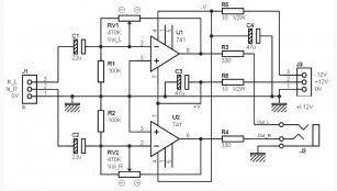
You can see this Headphones amplifier circuit more complete, since it shows all the components required for both left and right channels. Dont expect miracles from this type of circuit, the distortion can be quite important if you push too much volume. If you are looking for a headphone amp that sounds “loud and clear”, this amplifier will probably not live up to your expectations. But in ‘normal’ use, it is a good small Headphones amplifier.
(View)
View full Circuit Diagram | Comments | Reading(1390)
100W Basic MOSFET amplifier
Published:2013/3/13 1:04:00 Author:Ecco | Keyword: 100W , Basic MOSFET amplifier
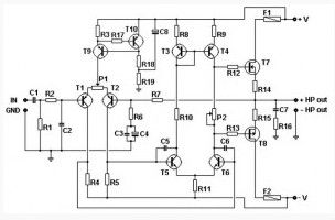
This Basic MOSFET amplifier is very simple to build and low cost. Is perfect for Hi-Fi amplifiers and instrument amplifiers (guitar, keyboards …). Output power is + / – 100 Wrms at 8 ohm load or + / – 160 Wrms below 4 ohms. The simplicity of this circuit cause distortion + / -0.1%. Bandwidth at -3 dB is from 4 Hz to 96 Khz and it is limited by C1, R1, R2 and C2.
Transistors T1 and T2 makes a first differential stage, current source of +/- 1 mA is set by R3. P1 allows a fine tuning of DC voltage at amplifier’s output. Place P1 at it’s half value for first power up, then turn it slowly for a lowest DC output voltage. It is recommended to use a first quality component.
Input sensitivity is 1.2 volts. The gain of 27x is archived by R7/R6. It may be modified by changing R7 value. Transistors T5 and T6 makes the second differential stage. Transistors T3 and T4 works as a current mirror source. They push the second differential stage to drain equal current. Doing so we get a high gain and an excellent linearity. Output MOSFET transistors works in AB class, their quiescient current is set from 50 to 100 mA trough P2.
(View)
View full Circuit Diagram | Comments | Reading(3807)
200 Watt MOSFET Amplifier
Published:2013/3/13 1:03:00 Author:Ecco | Keyword: 200 Watt, MOSFET Amplifier
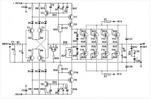
This circuit have Power output is 200 Wrms in 8 ohms or 350 Wrms into 4 ohms. Less than 0.02% distortion, damping factor greater than 300, the ratio signal / noise 112 dB (A balanced at full power), input sensitivity is 1.2 volts (200 W / 8 ohms).
Current source of + / – 1 mA carried around T5 and T6. Diodes D1 to D6 allow the use of low-noise type BC560C and BC550C transistors, transistor T7 to T10 is the driver stage. Potentiometer P1 allows setting the quiescent current of 100 mA per output transistor.
Symmetrical power entrusted to the large transformer 625 VA, 2 * 51 volts + bridge rectifier and 4700 uF capacitor 6, which gives the output voltage of + and – 70 volts per rail.
(View)
View full Circuit Diagram | Comments | Reading(3112)
5 Watt Audio Amplifier based LA4460
Published:2013/3/13 1:02:00 Author:Ecco | Keyword: 5 Watt, Audio Amplifier
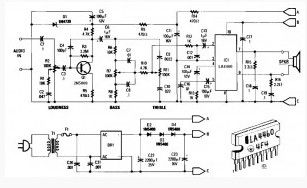
This 5 W audio power amplifier is built for general purpose and can drive speakers approximately 8 to 12 inches. This 5W power amplifier circuit is based on the Sanyo LA4460 IC which used as an audio output.
This Low-power amplifier circuit have built in loudness control, driver amplifier Q1, and the bass/treble controls of around ± 10 dB boost / cut. It would be useful in a wide variety of situations. Either displayed ac supply can be used, or 12 VDC supply can be connected to points A & B (positive) and C (negative).
For stereo circuit can be used two of this circuit by using ganged potentiometer at R2, R7 and R11. T1 is 12V at 1 ampere plug-in transformer.
(View)
View full Circuit Diagram | Comments | Reading(1618)
| Pages:17/250 1234567891011121314151617181920Under 20 |
Circuit Categories
power supply circuit
Amplifier Circuit
Basic Circuit
LED and Light Circuit
Sensor Circuit
Signal Processing
Electrical Equipment Circuit
Control Circuit
Remote Control Circuit
A/D-D/A Converter Circuit
Audio Circuit
Measuring and Test Circuit
Communication Circuit
Computer-Related Circuit
555 Circuit
Automotive Circuit
Repairing Circuit