
Amplifier Circuit
Index 2
Constituted by the INA128 AC-coupled instrumentation amplifier
Published:2014/5/19 20:43:00 Author:lynne | Keyword: Constituted by the INA128 AC-coupled instrumentation amplifier, INA128, OPA130
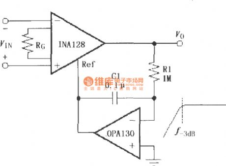
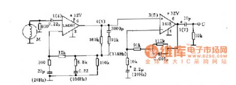
Constituted by the INA128 AC-coupled instrumentation amplifier circuit as shown:
As shown by instrumentation amplifier INA128 constitute communication coupling. OPA130 constitute the communication characteristics of feedback circuit (f - 3 db = 1/2 PI R1C1), the signal feedback to the Ref INA128 (5 feet), the coupled circuit of communication. (View)
View full Circuit Diagram | Comments | Reading(2522)
Composed of INA128 differential voltage to current conversion circuit
Published:2014/5/19 20:44:00 Author:lynne | Keyword: Composed of INA128 differential voltage to current conversion circuit, INA128
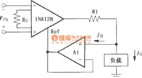
Composed of INA128 differential voltage to current conversion circuit shown as follow:
As shown by INA128 differential voltage to current conversion circuit. INA128 output by the R1 and A1 constitute a current source, output current Io is considered to be a constant, only related to the input voltage and R1, Io = (VIN/R1) x G. (View)
View full Circuit Diagram | Comments | Reading(1837)
Constituted by the INA131 differential voltage - current conversion circuit
Published:2014/5/19 20:35:00 Author:lynne | Keyword: Constituted by the INA131 differential voltage - current conversion circuit, INA131
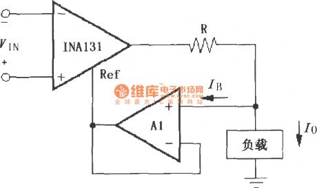
Constituted by the INA131 differential voltage - current conversion circuit as shown:
s shown constituted by the differential voltage INA131 - current conversion circuit. INA131 output constituted by the current sources A1 and R, because high input impedance operational amplifier, the bias current is extremely small, and the output current to the load is negligible compared to, so the output current Io can be considered constant, and only the input voltage and R about, Io = 100VIN / R (gain = 100). A1 Selection and IB error below. (View)
View full Circuit Diagram | Comments | Reading(1483)
Constituted by INA128, a cold junction compensation thermocouple amplifier
Published:2014/5/19 20:41:00 Author:lynne | Keyword: Constituted by INA128, a cold junction compensation thermocouple amplifier, INA128, REF102
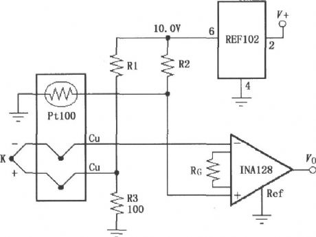
Constituted by INA128, a cold junction compensation thermocouple amplifier circuit as shown:
As shown INA128 constituted by cold junction compensation thermocouple amplifier. Using REF102 precision reference voltage source (10.0V) thermocouple power. Selection of the thermocouple and the resistance R1, R2 shown in the table match. (View)
View full Circuit Diagram | Comments | Reading(3393)
Constituted by INA131, the resistor bridge amplifier
Published:2014/5/18 20:36:00 Author:lynne | Keyword: Constituted by INA131, the resistor bridge amplifier, INA131
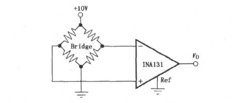
Constituted by INA131, the resistor bridge amplifier circuit as shown:
(View)
View full Circuit Diagram | Comments | Reading(1678)
Constituted by the INA131 AC-coupled instrumentation amplifier
Published:2014/5/18 20:34:00 Author:lynne | Keyword: Constituted by the INA131 AC-coupled instrumentation amplifier, INA131, OPA602
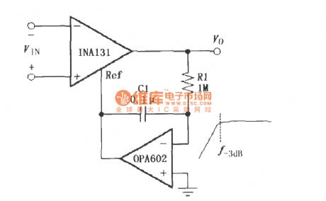
Constituted by the INA131 AC-coupled instrumentation amplifier circuit as shown:
As shown by INA131 instrumentation amplifier composed of AC-coupled. OPA602 constitute a feedback circuit with AC characteristics (f-3db = 1/2πR1C1), the signal is fed to the INA131's Ref side (5 feet), which formed the AC coupling circuit. (View)
View full Circuit Diagram | Comments | Reading(1539)
Constituted by the INA141 AC-coupled instrumentation amplifier
Published:2014/5/18 20:07:00 Author:lynne | Keyword: Constituted by the INA141 AC-coupled instrumentation amplifier, INA141, OPA602
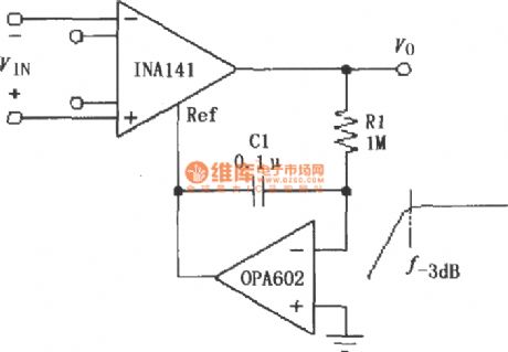
Constituted by the INA141 AC-coupled instrumentation amplifier circuit as shown:
As shown by the AC-coupled constitute INA141 instrumentation amplifier. OPA602 constitute a feedback circuit with AC characteristics (f-3db = 1/2πR1C1), the signal is fed to the INA141's Ref side (5 feet), which formed the AC coupling circuit. (View)
View full Circuit Diagram | Comments | Reading(1558)
Constituted by INA141 resistor bridge amplifier
Published:2014/5/18 20:25:00 Author:lynne | Keyword: Constituted by INA141 resistor bridge amplifier, INA141
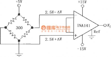
Constituted by INA141 resistor bridge amplifier circuit shown as follow:
(View)
View full Circuit Diagram | Comments | Reading(1560)
Composed of INA331/332 resistance bridge sensor amplifier
Published:2014/5/14 21:15:00 Author:lynne | Keyword: Composed of INA331/332 resistance bridge sensor amplifier, INA331, INA332
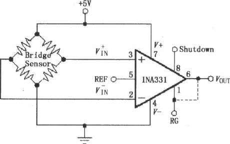
Composed of INA331/332 resistance bridge sensor amplifier circuit as shown:
(View)
View full Circuit Diagram | Comments | Reading(1772)
Composed of INAl28 resistance bridge amplifier
Published:2014/5/14 21:05:00 Author:lynne | Keyword: Composed of INAl28 resistance bridge amplifier, INA128
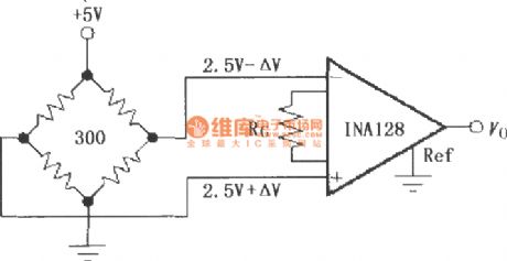
Composed of INAl28 resistance bridge amplifier circuit as shown:
(View)
View full Circuit Diagram | Comments | Reading(1590)
Using light emitting diode and the operational amplifier 400Hz sine wave circuit diagram
Published:2014/5/4 19:46:00 Author:lynne | Keyword: Using light emitting diode and the operational amplifier 400Hz sine wave circuit diagram, 741
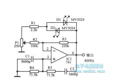
Using light emitting diode and the operational amplifier 400Hz sine wave circuit diagram as shown:
(View)
View full Circuit Diagram | Comments | Reading(2341)
Video amplifier circuit board diagram
Published:2014/4/24 21:01:00 Author:lynne | Keyword: Video amplifier board circuit diagram
Video amplifier circuit board diagram as shown:
(View)
View full Circuit Diagram | Comments | Reading(2065)
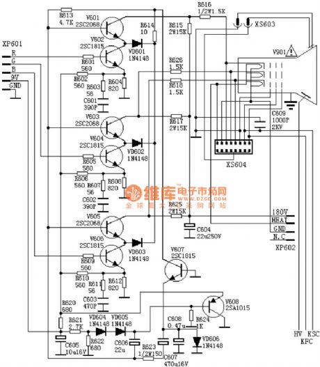
Praevia integrated amplifier infrared reception circuit diagram
Published:2014/4/23 20:10:00 Author:lynne | Keyword: Praevia integrated amplifier infrared reception circuit diagram
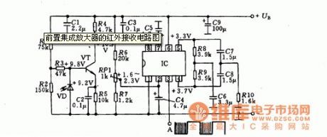
Praevia integrated amplifier infrared reception circuit diagram shown as follow:
(View)
View full Circuit Diagram | Comments | Reading(1746)
Ethernet interface circuit - DM9000 Network
Published:2014/4/20 20:49:00 Author:lynne | Keyword: Ethernet interface circuit - DM9000 Network, DM9000
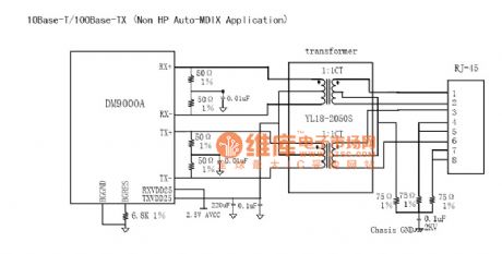
Ethernet interface circuit - DM9000 Network as shown:
(View)
View full Circuit Diagram | Comments | Reading(1724)
ND-1 amplification circuit diagram
Published:2014/4/16 20:39:00 Author:lynne | Keyword: ND-1 amplification circuit diagram
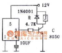
Amplified by the transistor drive current relay or power load.
(View)
View full Circuit Diagram | Comments | Reading(1377)
Platinum thermal resistance practical amplification circuit diagram
Published:2014/4/13 21:10:00 Author:lynne | Keyword: Platinum thermal resistance practical amplification circuit diagram
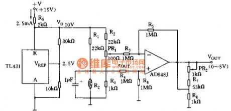
Platinum thermal resistance practical amplification circuit diagram shown as follow:
(View)
View full Circuit Diagram | Comments | Reading(1518)
The digital circuit composed of amplifier circuit diagram
Published:2014/4/7 21:36:00 Author:lynne | Keyword: The digital circuit composed of amplifier circuit diagram
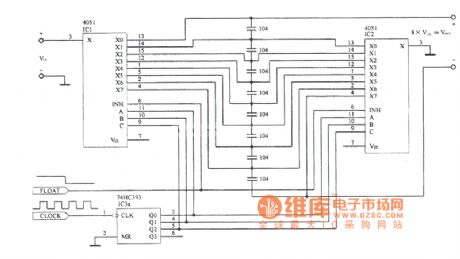
The digital circuit composed of amplifier circuit diagram as shown:
(View)
View full Circuit Diagram | Comments | Reading(1450)
Thyristor drive amplifier circuit diagram
Published:2014/4/3 20:44:00 Author:lynne | Keyword: Thyristor drive amplifier circuit diagram
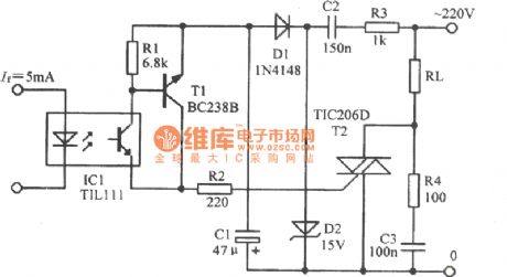
Thyristor drive amplifier circuit diagram as shown:
(View)
View full Circuit Diagram | Comments | Reading(2081)
Phonograph amplifier circuit diagram
Published:2014/4/3 20:41:00 Author:lynne | Keyword: Phonograph amplifier circuit diagram
Phonograph amplifier circuit diagram shown as follow:
(View)
View full Circuit Diagram | Comments | Reading(1773)
High-voltage amplification circuit diagram of SCR
Published:2014/4/3 20:39:00 Author:lynne | Keyword: High-voltage amplification circuit diagram of SCR
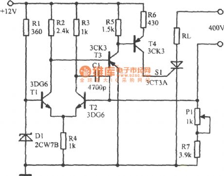
High-voltage amplification circuit diagram of SCR as shown:
(View)
View full Circuit Diagram | Comments | Reading(1965)
| Pages:2/250 1234567891011121314151617181920Under 20 |
Circuit Categories
power supply circuit
Amplifier Circuit
Basic Circuit
LED and Light Circuit
Sensor Circuit
Signal Processing
Electrical Equipment Circuit
Control Circuit
Remote Control Circuit
A/D-D/A Converter Circuit
Audio Circuit
Measuring and Test Circuit
Communication Circuit
Computer-Related Circuit
555 Circuit
Automotive Circuit
Repairing Circuit