
Amplifier Circuit
Index 10
Amplifier Timer electronic circuit
Published:2013/4/1 3:00:00 Author:Ecco | Keyword: Amplifier Timer
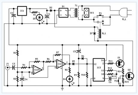
View full Circuit Diagram | Comments | Reading(1154)
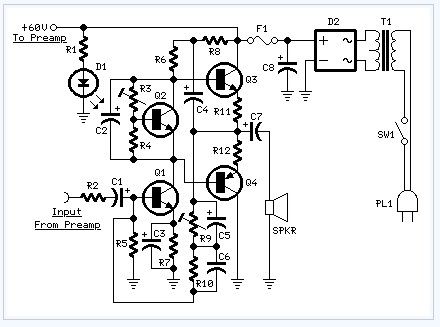
Amplifier Of Acoustic Frequencies And Preamplifier electronic circuit
Published:2013/4/1 2:59:00 Author:Ecco | Keyword: Amplifier, Acoustic Frequencies, Preamplifier
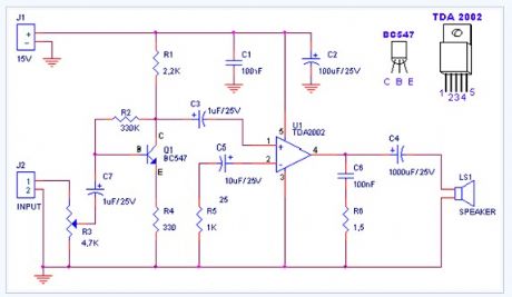
Tendency of catering: 15VForce of expense: 4,2Wrms in the 4WMinimal signal of entry: 94mVp-p with preamplifier, 0,65Vp-p without the preamplifier.
(View)
View full Circuit Diagram | Comments | Reading(1210)
Amplified Ear electronic circuit
Published:2013/4/1 2:57:00 Author:Ecco | Keyword: Amplified Ear
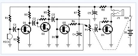
The heart of the circuit is a constant-volume control amplifier. All the signals picked-up by the microphone are amplified at a constant level of about 1 Volt peak to peak. In this manner very low amplitude audio signals are highly amplified and high amplitude ones are limited. This operation is accomplished by Q3, modifying the bias of Q1 (hence its AC gain) by means of R2. A noteworthy feature of this circuit is 1.5V battery operation. Typical current drawing: 7.5mA.
(View)
View full Circuit Diagram | Comments | Reading(1615)
60w Linear Amplifier electronic circuit diagram
Published:2013/4/1 2:56:00 Author:Ecco | Keyword: 60w Linear Amplifier
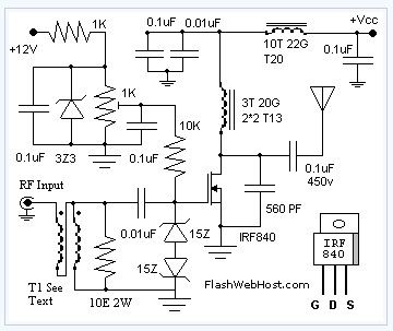
The 60 Watt linear amplifier is simple all solid state circuit using power mosfet IRF840. The IRF series of power transistors are available in various voltage and power ratings. A single IRF840 can handle maximum power output of 125 watts. Since these transistors are used in inverters and smps they are easily available for around Rs: 20/-.The IRF linear amplifier can be connected to the out put of popular VWN-QRP to get an output of 60 Watts. The circuit draws 700 ma at 60 Volt Vcc. Good heat sink is a must for the power transistor.Alignment of the circuit is very easy. Connect a dummy load to the out put of the circuit. You can use some small bulb like 24V 6Watts as the dummy load. I have even used 230V 60Watts bulb as dummy load with my IRF840 power amplifier working at 120Volts. Adjust the 10K preset to get around 100 ma Drain current. I used gate voltage of 0.8V with my linear amplifier. A heigh gate voltage can make the power transistor get distroyed by self oscillation. So gate voltage must be below 2V and fixing at 1V will be safe.Bifalar transformaer T1 is wound with 8 turns 26SWG on 1.4 x 1 balun core.The coil on the drain of IRF is 3 turns 20 SWG wound on 4 number of T13.9 torroids (two torroids are stacked to form a balun core). The RFC at the Vcc line is 20 Turns 20 SWG wound on T20 torroid.
(View)
View full Circuit Diagram | Comments | Reading(3064)
60w Guitar Amplifier electronic circuit diagram
Published:2013/4/1 2:54:00 Author:Ecco | Keyword: 60w Guitar Amplifier
Bass, Treble, Harmonic modifier and Brightness controls. Output power: 40W on 8 Ohm and 60W on 4 Ohm loads
(View)
View full Circuit Diagram | Comments | Reading(1744)
50 Watt Amplifier electronic circuit diagram
Published:2013/4/1 2:50:00 Author:Ecco | Keyword: 50 Watt Amplifier
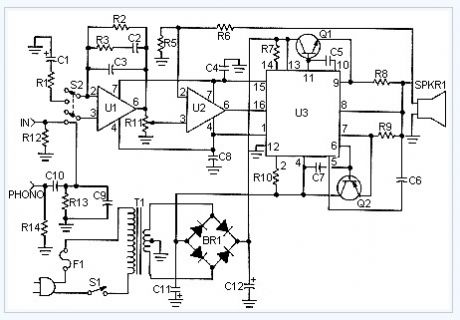
This is a handy, easy to build general purpose 50 watt amp. The amp has an input for a radio, TV, stereo or other line level device. It also has a phono input for a record player, guitar, microphone or other un-amplified source. With the addition of a low pass filter at the input, it makes a great amp for a small subwoofer.
(View)
View full Circuit Diagram | Comments | Reading(1265)
5-band Graphic Equalizer electronic circuit diagram
Published:2013/4/1 2:49:00 Author:Ecco | Keyword: 5-band Graphic Equalizer
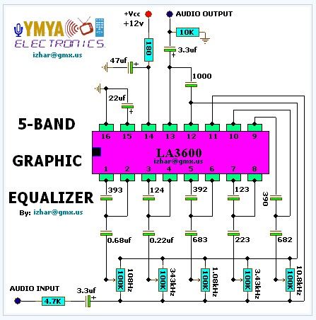
This complete high quality, low noise 5-BAND GRAPHIC EQUALIZER circuit is based around Monolithic Linear integrated circuit LA3600 manufactured by SANYO. This circuit is very easy to build and has good Quality. You can use it with Portable component stereos, tape-recorders, radio-cassette recorders, car stereos etc... It is On-chip one operational amplifier. 5-band graphic equalizer for one channel can be formed easily by externally connecting capacitors and variable resistors which fix fo (resonance frequency). Series connection of two LA3600�s makes multiband (6 to 10 bands) available. It is Highly stable to capacitive load. Maximum supply voltage VCC max 20V must not be exceeded. The operating voltage is in the range of 5 to 15V. Application of power with the pin-to-pin spaces shorted causes breakdown or deterioration of the IC to occur. When mounting the IC on the board or applying power, make sure that the pin-to-pin spaces are not shorted with solder, etc.
(View)
View full Circuit Diagram | Comments | Reading(2558)
3 Transistor Audio Amp electronic circuit diagram
Published:2013/4/1 2:48:00 Author:Ecco | Keyword: 3 Transistor Audio Amp
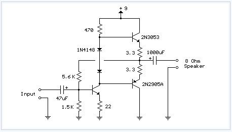
Here is a little audio amplifier similar to what you might find in a small transistor radio. The input stage is biased so that the supply voltage is divided equally across the two complimentary output transistors which are slightly biased in conduction by the diodes between the bases. A 3.3 ohm resistor is used in series with the emitters of the output transistors to stabilize the bias current so it doesn't change much with temperature or with different transistors and diodes. As the bias current increases, the voltage between the emitter and base decreases, thus reducing the conduction. Input impedance is about 500 ohms and voltage gain is about 5 with an 8 ohm speaker attached. The voltage swing on the speaker is about 2 volts without distorting and power output is in the 50 milliwatt range. A higher supply voltage and the addition of heat sinks to the output transistors would provide more power. Circuit draws about 30 milliamps from a 9 volt supply.
(View)
View full Circuit Diagram | Comments | Reading(2287)
3 Channel Spectrum Analyzer electronic circuit diagram
Published:2013/4/1 2:47:00 Author:Ecco | Keyword: 3 Channel Spectrum Analyzer
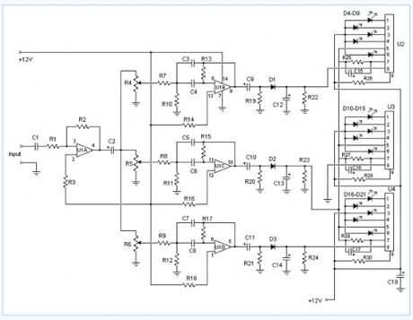
This 3 channel 15 LED spectrum analyzer is the perfect addition to any audio amp project. It produces fantastic displays on three LED bars that can be individually adjusted for any particular frequency range. The circuit will take line level output from most any audio source, and operates on 12V DC. This means that it can even be run in a car.
(View)
View full Circuit Diagram | Comments | Reading(3856)
2n3055 Power Amplifier 60w electronic circuit diagram
Published:2013/4/1 2:45:00 Author:Ecco | Keyword: Power Amplifier
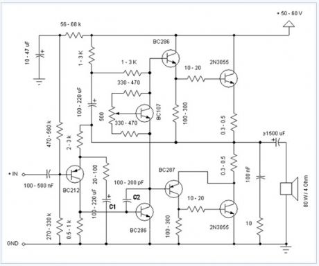
Simple and low cost. The optimal supply voltage is around 50V, but this amp work from 30 to 60V. The maximal input voltage is around 0.8 - 1V. As you can see, in this design the components have a big tolerance, so you can build it almost of the components, which you find at home. The and transistors can be any NPN type power transistor, but do not use Darlington types... The output power is around 60W.
(View)
View full Circuit Diagram | Comments | Reading(3024)
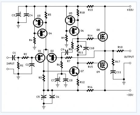
25w Mosfet Audio Amplifier electronic circuit
Published:2013/4/1 2:44:00 Author:Ecco | Keyword: 25w, Mosfet Audio Amplifier
View full Circuit Diagram | Comments | Reading(1998)
22 Watt Audio Amplifier electronic circuit diagram
Published:2013/4/1 2:43:00 Author:Ecco | Keyword: 22 Watt Audio Amplifier
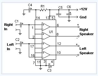
The 22 watt amp is easy to build, and very inexpensive. The circuit can be used as a booster in a car audio system, an amp for satellite speakers in a surround sound or home theater system, or as an amp for computer speakers. The circuit is quite compact and uses only about 60 watts.
(View)
View full Circuit Diagram | Comments | Reading(1801)
20w Bridge Audio Amplifier electronic circuit
Published:2013/4/1 2:42:00 Author:Ecco | Keyword: 20w, Bridge Audio Amplifier
View full Circuit Diagram | Comments | Reading(1374)
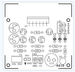
20w Audio Amplifier Using Lm1875 electronic circuit
Published:2013/4/1 2:41:00 Author:Ecco | Keyword: 20w Audio Amplifier
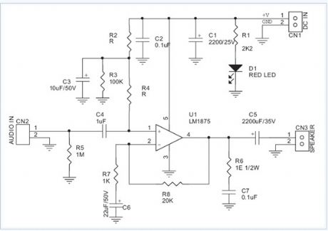
View full Circuit Diagram | Comments | Reading(1701)
200w Audio Amplifier electronic circuit
Published:2013/4/1 2:39:00 Author:Ecco | Keyword: 200w Audio Amplifier
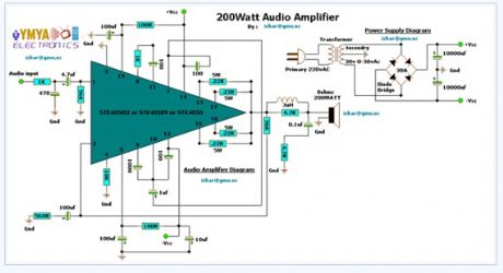
Output Power : 200WattsLoad Resistance : 8ohmsInput impedance : 55KMaximum supply voltage : (+95v)-0-(-95v)Recommended supply voltage : (+66v)-0-(-66v)This complete high quality, low noise mono audio power amplifier is based around the Hybrid Integrated Circuit STK4050 manufactured by Sanyo. The circuit incorporates volume and has a maximum music output power of 200W.The circuit incorporates an on board power supply; therefore, only centre tapped transformer is required to power the circuit. I t has very good quality sound. U can use it with your Home Theatre your PC & etc... You can also use it as Subwoofer Amplifier. It is a compact package for THIN-TYPE Audio sets. Easy Heatsink design to disperse heat generated in THIN-TYPE audio sets. Constant-Current circuit to Reduce supply switch-ON and switch-OFF shock noise. External supply switch-On and switch-OFF shock noise muting, Load short-circuit protection, thermal shutdown and other circuits can be tailored-designed.
(View)
View full Circuit Diagram | Comments | Reading(1996)
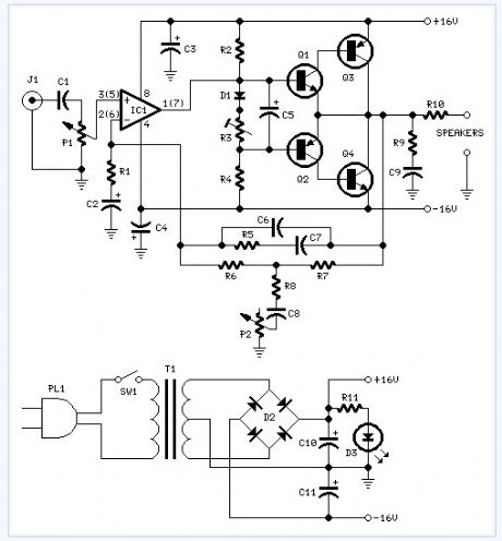
18w Audio Amplifier electronic circuit
Published:2013/4/1 2:36:00 Author:Ecco | Keyword: 18w Audio Amplifier
Amplifier parts: P1 = 22K Log.Potentiometer (Dual-gang for stereo)R1 = 1K 1/4W ResistorR2 = 4K7 1/4W ResistorR3 = 100R 1/4W ResistorR4 = 4K7 1/4W ResistorR5 = 82K 1/4W ResistorR6 = 10R 1/2W ResistorR7 = R22 4W Resistor (wirewound)R8 = 1K 1/2W Trimmer Cermet (optional)C1 = 470nF 63V Polyester CapacitorC2,C5 = 100΅F 3V Tantalum bead CapacitorsC3,C4 = 470΅F 25V Electrolytic CapacitorsC6 = 100nF 63V Polyester CapacitorD1 = 1N4148 75V 150mA DiodeIC1 = TLE2141C Low noise,high voltage,high slew-rate Op-ampQ1 = BC182 50V 100mA NPN TransistorQ2 = BC212 50V 100mA PNP TransistorQ3 = TIP42A 60V 6A PNP TransistorQ4 = TIP41A 60V 6A NPN TransistorJ1 RCA audio input socket
(View)
View full Circuit Diagram | Comments | Reading(1766)
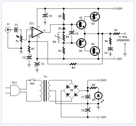
15 Watt Amplifier electronic circuit
Published:2013/4/1 2:35:00 Author:Ecco | Keyword: 15 Watt Amplifier
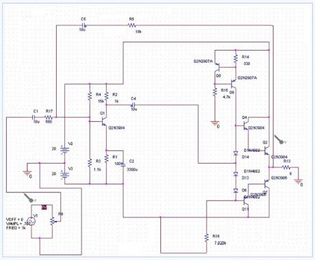
This amplifier uses a dual 20 Volt power supply and delivers 15 watts RMS into an 8 ohm load. Q1 operates in common emitter, the input signal being passed to the bias chain consisting of Q8, Q9, D6, D13 and D14. Q8 and Q9 provide a constant current through the bias chain to minimize distortion, the output stage formed by a discrete darlington pair (Q2,Q4) and (Q7,Q11). The last two transistors are power Transitors, specifically the 2N3055 and MJ2955. The 7.02K resistor, R16 was made using a series combination of a 4.7K, 680 Ohms, and two 820 Ohms. The 1.1K resistor, R3 was made using a 100 Ohms and a 1K resistor. You can use this circuit with any walkman or CD player since it is designed to take a standard 500mv RMS signal.
(View)
View full Circuit Diagram | Comments | Reading(1058)
10w Audio Amplifier With Bass-boost electronic circuit
Published:2013/4/1 2:35:00 Author:Ecco | Keyword: 10w Audio Amplifier, Bass-boost
This design is based on the 18 Watt Audio Amplifier, and was developed mainly to satisfy the requests of correspondents unable to locate the TLE2141C chip. It uses the widespread NE5532 Dual IC but, obviously, its power output will be comprised in the 9.5 - 11.5W range, as the supply rails cannot exceed ±18V.As amplifiers of this kind are frequently used to drive small loudspeaker cabinets, the bass frequency range is rather sacrificed. Therefore a bass-boost control was inserted in the feedback loop of the amplifier, in order to overcome this problem without quality losses. The bass lift curve can reach a maximum of +16.4dB @ 50Hz. In any case, even when the bass control is rotated fully counterclockwise, the amplifier frequency response shows a gentle raising curve: +0.8dB @ 400Hz, +4.7dB @ 100Hz and +6dB @ 50Hz (referred to 1KHz).
(View)
View full Circuit Diagram | Comments | Reading(1680)
10w Mini Audio Amplifier electronic circuit
Published:2013/4/1 2:34:00 Author:Ecco | Keyword: 10w, Mini Audio Amplifier
You can use this powerfull amplifier in any small audio project. It is very small (6.5 x 4.5 cm).It outputs 10W and uses a 9V battery.
(View)
View full Circuit Diagram | Comments | Reading(1723)
Remote Sensor System Pre-Amp circuit
Published:2013/3/29 4:43:00 Author:Ecco | Keyword: Remote Sensor System, Pre-Amp
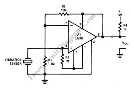
Remote sensor might cause a trouble if it’s a passive type, has very low power output, and should be connected with relatively long cables. By supplying a current or voltage source through its connection wire, it’s possible to make long enough wiring without suffering much noise/interference. The following schematic diagram show a circuit consist of LM10 to make a remote vibration sensor connection works fine. We don’t need a separate wires for signal and power supply, we send them on the same cable pair! Here is the schematic diagram of the circuit:
(View)
View full Circuit Diagram | Comments | Reading(1245)
| Pages:10/250 1234567891011121314151617181920Under 20 |
Circuit Categories
power supply circuit
Amplifier Circuit
Basic Circuit
LED and Light Circuit
Sensor Circuit
Signal Processing
Electrical Equipment Circuit
Control Circuit
Remote Control Circuit
A/D-D/A Converter Circuit
Audio Circuit
Measuring and Test Circuit
Communication Circuit
Computer-Related Circuit
555 Circuit
Automotive Circuit
Repairing Circuit