
Amplifier Circuit
Index 12
TDA8929T Class-D Audio Power Amplifier
Published:2013/3/26 3:35:00 Author:Ecco | Keyword: Class-D , Audio Power Amplifier
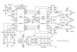
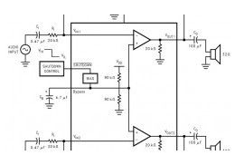
The following diagram is the circuit diagram of Class-D audio power amplifier which built based on power chip TDA8929T. About TDA8929T: The power IC TDA8929T is the controller of a two-chip set for a high efficiency class-D audio power amplifier system. The system is divided into two chips: TDA8929T; the analog controller chip inside a SO24 package TDA8926J/ST/TH or TDA8927J/ST/TH.
(View)
View full Circuit Diagram | Comments | Reading(1853)
Electro Harmonix Graphic Equalizer
Published:2013/3/26 3:17:00 Author:Ecco | Keyword: Electro Harmonix , Graphic Equalizer
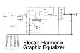
This is the diagram od electro-harmonix graphic equalizer. You can specify the number of channels according to your needs. You just need to parallel the components: C1, C2, R1, an om-amp, Potensiometer and a 470 ohm resistor. The frequency to be boost decided by C1, C2 and R1. See the diagram for the C1, C2 and R1 combination versus the frequency.
(View)
View full Circuit Diagram | Comments | Reading(1175)
4W Stereo Amplifier using LM2877
Published:2013/3/26 3:14:00 Author:Ecco | Keyword: 4W Stereo Amplifier
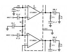
This is the diagram of 4W stereo power amplifier built based stereo power IC LM2877 with a few of external components. The circuit required single power supply with voltage range of 6VDC – 24VDC. Heatsink is a must to prevent over heating on the IC.
(View)
View full Circuit Diagram | Comments | Reading(1009)
Stereo Tube Amplifier 4 Watts
Published:2013/3/26 3:09:00 Author:Ecco | Keyword: Stereo Tube Amplifier, 4 Watts
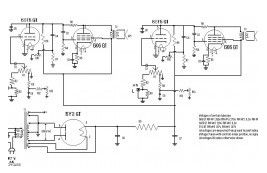
This is the circuit diagram of stereo tube amplifier using 6SQ7-GT and 6V6-GT. The tube amplifier circuit is uses the total of 5 power vacuum tube. The diagram is based on the output section design of typical late 1940′s old AM Trutone radio with 6 tubes. The output will be 4 Watts per channel (2x4W stereo tube amplifier)
(View)
View full Circuit Diagram | Comments | Reading(1618)
LM4809 Stereo 105mW Headphone Amplifier
Published:2013/3/26 3:07:00 Author:Ecco | Keyword: Stereo, 105mW, Headphone Amplifier
This is the stereo headphone amplifier circuit diagram, built based LM4809. This circuit can be used for stereo headphone amplifier circuit for home audio system, microphone preamplifier, personal computers and PDA headphone amplifier and more. The LM4809 is known as a stereo audio power amplifier capable of delivering 105mW per channel of continuous average power into a 16O load with 0.1% (THD+N) from a 5V power supply.
(View)
View full Circuit Diagram | Comments | Reading(1028)
1W Stereo Headphone Amplifier based TDA2822
Published:2013/3/26 3:04:00 Author:Ecco | Keyword: 1W, Stereo Headphone Amplifier
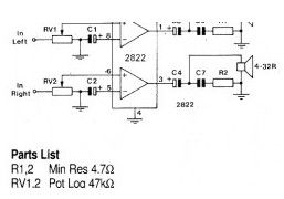
Above circuit diagram is the schematic of 1W stereo headphone amplifier. The circuit is built based TDA2822, designed for use in portable players, radios and other common electronic devices which can use headphone for the audio output.
(View)
View full Circuit Diagram | Comments | Reading(2103)
4W Bridge Amplifier using LM388
Published:2013/3/26 3:02:00 Author:Ecco | Keyword: 4W Bridge Amplifier
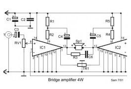
Parts List: R1-2-4-5=270Ω R3 = 2.7Ω VR1 = 10KΩ Log. Pot. TR1 = 470KΩ Trimmer IC1-2 = LM388 C1 = 100uF/25V C2 = 100nF C3 = 10uF/25V C4-5 = 22uF/25V C6 = 47nF.
(View)
View full Circuit Diagram | Comments | Reading(1094)
65W Power Amplifier using HEXFET
Published:2013/3/26 3:01:00 Author:Ecco | Keyword: 65W Power Amplifier , HEXFET
This is a high quality 65W power amplifier circuit based HEXFET IRF9540 and IRF540. The circuit is quite simple for amplifier with good sound quality. The component parts is easy to find at electronic store around your place. It uses split power supply. Q8, Q10, Q11, Q12, Q13 should be mounted on heatsink for thermic stability.
(View)
View full Circuit Diagram | Comments | Reading(2218)
1500W Power Amplifier
Published:2013/3/26 3:01:00 Author:Ecco | Keyword: 1500W, Power Amplifier
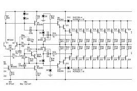
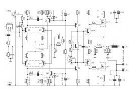
This is a very high 1500W power amplifier circuit diagram by Rod Elliott. The circuit is built using 10 pairs of power transistor MJ15024 and MJ15025 (or MJ21193/MJ21194), then it will use 20 pieces of power transistor for final amplification.
(View)
View full Circuit Diagram | Comments | Reading(4348)
150W Power Amplifier
Published:2013/3/26 3:00:00 Author:Ecco | Keyword: 150W , Power Amplifier
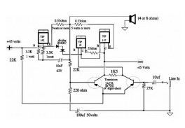
This is the very simple circuit diagram of 150W power amplifier. The circuit is easy enough to built without PCB. The power output range is about 100-150W depends to the power supply and the Darlington’s you use for the amplifier. Heatsink is a must since the final transistor is going to hot when the amplifier is activated.
(View)
View full Circuit Diagram | Comments | Reading(1873)
Mic Condenser Amplifier
Published:2013/3/25 4:31:00 Author:Ecco | Keyword: Mic Condenser Amplifier
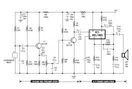
This is the circuit diagram of mic condenser amplifier. The low-cost and compact mic condenser audio amplifier described right here is deliver good-quality audio of 0.5 watts at 4.5 volts. It could possibly be applied as a part of low-power transmitters, packet radio receivers, intercoms and walkie-talkies.
(View)
View full Circuit Diagram | Comments | Reading(1375)
Meter/ Data Acquisition Amplifier
Published:2013/3/25 3:35:00 Author:Ecco | Keyword: Meter, Data, Acquisition Amplifier
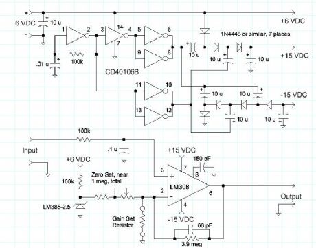
The LM385-2.5 injects current into the summing node through an adjustable resistor with a value near 1 megohm. A good-quality fixed resistor near 900k and a 200k potentiometer would be a good combination. The zero pot is adjusted to get an output near -10 volts with the input grounded (assuming -10 volts is the negative limit of the data acquisition device - other offsets are possible). The gain will be near 5 with no gain set resistor, and will reach about 100 with a 41k resistor. The zero might vary slightly when the gain is changed. Use a good-quality 3.9 megohm resistor. Lower values may be used for all the gain-setting resistors.
(View)
View full Circuit Diagram | Comments | Reading(1184)
Class-A Audio Amplifiers
Published:2013/3/25 3:25:00 Author:Ecco | Keyword: Class-A Audio Amplifier
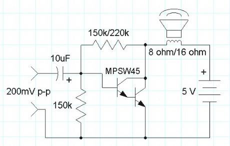
A class-A audio amplifier is pretty wasteful of power but when plenty of power is available the simplicity is attractive. Here is a simple darlington transistor example intended for use with a 5 volt power supply:
(View)
View full Circuit Diagram | Comments | Reading(1309)
Crystal Radio (and other purpose) Audio Amplifier
Published:2013/3/25 3:25:00 Author:Ecco | Keyword: Crystal Radio , Audio Amplifier
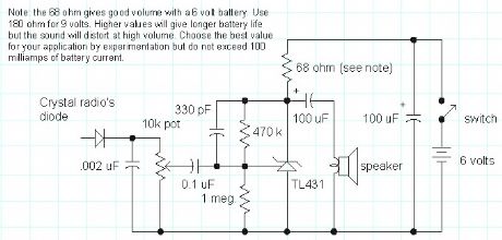
Here is a simple audio amplifier using a TL431 shunt regulator. The amplifier will provide room-filling volume from an ordinary crystal radio outfitted with a long-wire antenna and good ground. The circuitry is similar in complexity to a simple one-transistor radio but the performance is superior (with the exception of the amazing one-transistor reflex ). The TL431 is available in a TO-92 package and it looks like an ordinary transistor so your hobbyist friends will be impressed by the volume you are getting with only one transistor and the amplifier may be used for other projects, too. Higher impedance headphones and speakers may also be used. An earphone from an old telephone will give ear-splitting volume and great sensitivity! The 68 ohm resistor may be increased to several hundred ohms when using high impedance earphones to save battery power.
(View)
View full Circuit Diagram | Comments | Reading(1742)
Op-Amp Audio Amplifier
Published:2013/3/25 3:24:00 Author:Ecco | Keyword: Op-Amp Audio Amplifier
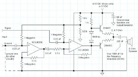
The above circuit is a versatile audio amplifier employing a low cost LM358 op-amp. The differential inputs give the amplifier excellent immunity to common-mode signals which are a common cause of amplifier instability. The dotted ground connection represents the wiring in a typical project illustrating how the ground sensing input can be connected to the ground at the source of the audio instead of at the amplifier where high currents are present. If the source is a power supply referenced signal then one of the amplifier inputs is connected to the positive supply. For example, an NPN common-emitter preamplifier may be added for very high gain and by connecting the differential inputs across the collector resistor instead of from collector to ground, destabilizing feedback via the power supply is greatly reduced.
(View)
View full Circuit Diagram | Comments | Reading(2138)
Computer Audio Booster
Published:2013/3/25 3:23:00 Author:Ecco | Keyword: Computer Audio Booster
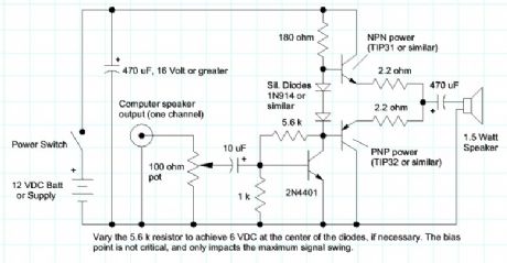
Here is a simple amplifier for boosting the audio level from low-power sound cards or other audio sources driving small speakers like toys or small transistor radios. The circuit will deliver about 2 watts as shown. The parts are not critical and substitutions will usually work. The two 2.2 ohm resistors may be replaced with one 3.9 ohm resistor in either emitter.
(View)
View full Circuit Diagram | Comments | Reading(1866)
Curiously Low Noise Amplifier
Published:2013/3/25 3:22:00 Author:Ecco | Keyword: Low Noise Amplifier
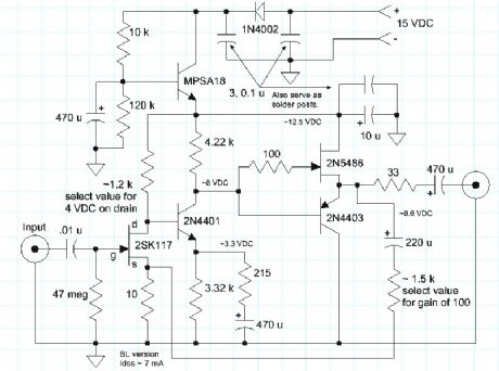
The Curiously Low Noise Amplifier takes advantage of the wonderful noise characteristics of the 2SK170 JFET that boasts a noise voltage below 1 nV/root-Hz and virtually no noise current. The noise voltage of the amplifier is only 1.4 nV/root-Hz at 1 kHz, increasing to only 2.7 nV/root-Hz at 10 Hz. The noise current is difficult to measure, so this simple utility amplifier can see the noise from a 50 ohm resistor and a 100k resistor, too. (The 1.4 nV input-referred noise will increase to about 1.7 nV with a 50 ohm resistor, instead of a short, and a 100k resistor will give an input-referred noise near 40 nV, with very little contribution from the amplifier.)
This amplifier is a utility amplifier with a gain of 100, that would typically be used in a lab setting to boost tiny signals for measurement or further processing. It isn't intended to drive a speaker or headphones directly. (It could drive the LM386 quite nicely.) The circuit is a simple discrete transistor feedback circuit with two gain stages and a unique class-A output buffer:
(View)
View full Circuit Diagram | Comments | Reading(2037)
Simple LM386 Audio Amplifier
Published:2013/3/25 3:21:00 Author:Ecco | Keyword: Audio Amplifier
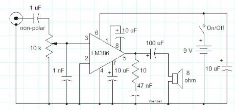
This simple amplifier shows the LM386 in a high-gain configuration (A = 200). For a maximum gain of only 20, leave out the 10 uF connected from pin 1 to pin 8. Maximum gains between 20 and 200 may be realized by adding a selected resistor in series with the same 10 uF capacitor. The 10k potentiometer will give the amplifier a variable gain from zero up to the maximum.
(View)
View full Circuit Diagram | Comments | Reading(2264)
Stereo Pre-amplifier + Tone Control Circuit based TDA1524A
Published:2013/3/18 2:05:00 Author:Ecco | Keyword: Stereo , Pre-amplifier, + Tone Control
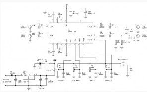
This is the circuit diagram of stereo preamplifier which built based a compact IC TDA1524A. Tone control circuit module is included in this preamplifier circuit, so you can connect the output channels directly to stereo power audio amplifier circuit.
(View)
View full Circuit Diagram | Comments | Reading(3066)
1W Audio Amplifier Circuit based TDA7052
Published:2013/3/18 2:03:00 Author:Ecco | Keyword: 1W , Audio Amplifier
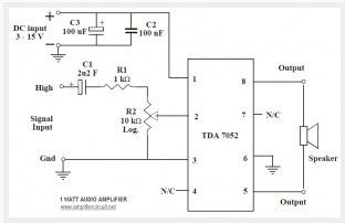
This is the 1 Watt power audio amplifier based Phillip IC TDA7052. The circuit can be used for small audio amplification. The circuit is very simple and easy to build. It only required 5 external components to support the main power IC. Ideal supply voltage is 6V to 12 VDC. R2 is a linear potensiometer to adjust the volume.
(View)
View full Circuit Diagram | Comments | Reading(2216)
| Pages:12/250 1234567891011121314151617181920Under 20 |
Circuit Categories
power supply circuit
Amplifier Circuit
Basic Circuit
LED and Light Circuit
Sensor Circuit
Signal Processing
Electrical Equipment Circuit
Control Circuit
Remote Control Circuit
A/D-D/A Converter Circuit
Audio Circuit
Measuring and Test Circuit
Communication Circuit
Computer-Related Circuit
555 Circuit
Automotive Circuit
Repairing Circuit