
Amplifier Circuit
Index 38
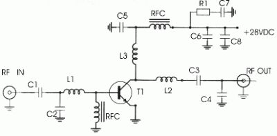
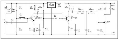
RF Preamplifier
Published:2012/11/15 0:49:00 Author:muriel | Keyword: RF Preamplifier
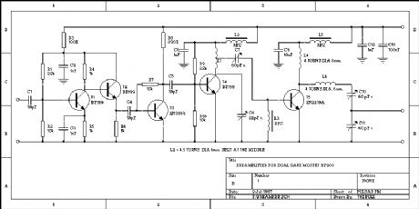
Input needs only several mWatts (e.g. BF900) -> 300 mWatts OUT. This schematic is a often used buffer. It's easy to build, clean and cheap. When you want even more power, you can replace the 2N2219a by a 2N4427 or 2N3553. You can lower the output by adding a little resistor (10..47 Ohm 1/2W) in the emitter line of the 2N2219a. (View)
View full Circuit Diagram | Comments | Reading(5971)
DA6340 VCR infrared remote control receiver preamplifier circuit
Published:2012/11/14 20:03:00 Author:Ecco | Keyword: VCR, infrared, remote control , receiver, preamplifier
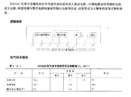
BA6340 is suitable for the VCR 's infrared remote control receiver preamplifier integrated circuit. Internal circuit consists of the signal receiving circuit, amplifier circuit, peak detector, shaping circuit and the Schmitt output circuit, etc. It uses 8-pin single in-line plastic package.
(View)
View full Circuit Diagram | Comments | Reading(1165)
8W Broadband FM RF Amplifier
Published:2012/11/14 0:34:00 Author:muriel | Keyword: 8W, Broadband , FM, RF Amplifier

Here's 8W broadband FM RF amplifier using 2SC1971 VHF power transistor. The RF Amplifier PCB layout designed for FM broadband 88-108 MHz transmitters using microstripline technique. This 8W RF amplifier circuit provides an appropriate power boost for transmitters with an input of 500 mW. (View)
View full Circuit Diagram | Comments | Reading(3750)
80W RF Amplifier 88-108 MHz
Published:2012/11/14 0:32:00 Author:muriel | Keyword: 80W, RF Amplifier, 88-108 MHz
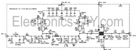
This is 80W RF power amplifier that boosts FM Transmitter's power using 2SC2782 bipolar transistors in a tuned class C circuit. RF amplifier can be driven to full 80W power with less than 1 watt driving input power, so that a large gain margin results in this FM transmitter. To obtain stability in this RF amplifier, I employed several techniques, such as placing the resonances of base and collector chokes far apart, damping the chokes with resistors, using RC combinations for absorption of unwanted frequencies, using feed trough capacitors for bypassing on the board, etc. It took some tweaking, but the amplifier ended up unconditionally stable.
This amplifier has a low-pass filter at the output, resulting in a signal clean enough to be directly connected to an antenna. The SWR meter was placed before the filter, in order to clean out the harmonics produced by its diodes. In any case, while the signal is clean enough to easily satisfy usual legal and technical requirements, this transmitter should not be used at a multi-transmitter site without further narrow band filtering! This is so because any other strong signals on nearby frequencies would be picked up by the antenna and coupled to the power transistor, which would mix it up with the own signal, creating a wide array of intermodulation products, some of which would be re-radiated! This is a common and very big problem in many multi transmitter sites. In such places, not even one FM transmitter should be allowed on the air without narrow band filtering! Such filtering is easily accomplished by means of a single tuned cavity, which can be constructed from copper tubing or sheet. (View)
View full Circuit Diagram | Comments | Reading(3168)
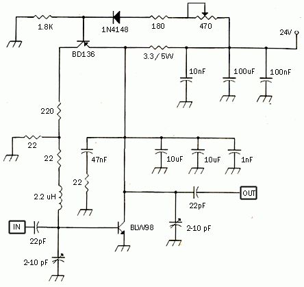
5 Watts FM RF Amplifier
Published:2012/11/13 21:53:00 Author:muriel | Keyword: 5 Watts , FM, RF Amplifier
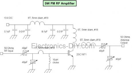
This fm rf amplifier uses 2SC1971 transistor to provide 5 watts of output. Output matching is adjusted via the two 40pF trimmer capacitors likewise also to the input. Note that the emitter of this transistor is directly grounded on the heat sink and should have a good thermal transfer. Driving power of 100 to 200mW can be applied in order to provide 5watts of output. Use a dummy load to tune this amplifier and remember that the transistor is biased in Class C, sufficient filtering should be followed after the output to minimize all the harmonics. Use ground plane construction technique in the PCB lay-out for best result, the more the grounding the better. If you have hard time finding the 10uH rf choke, try to wind 1/2 meter of 0.2mm enamel wire over a 33K 1/2 watt resistor and solder the coil ends to the legs of the resistor. (View)
View full Circuit Diagram | Comments | Reading(4105)
5 Watt UHF TV Amplifier
Published:2012/11/13 21:48:00 Author:muriel | Keyword: 5 Watt , UHF , TV Amplifier
This small circuit is a Linear amplifier for driving small UHF TV transmitters. Its gain is 7dB and can amplify a signal between 450-800 MHz. You can drive the circuit with 1 to 1,5 Watts signal. Better use double layer PCB with the second layer connected to earth. Use a stabilized power supply 25 volts and at least 5Amps. The transistor case is the SOT-122A and be careful because the transistor is very toxic for your health. Tuning can be achieved turning the two variable capacitors. Do not forget to use heat sink for both transistors, specially for the BLW89 and it would be better if you place a small fan as well. (View)
View full Circuit Diagram | Comments | Reading(1951)
5 Watt FM Amplifier
Published:2012/11/13 21:47:00 Author:muriel | Keyword: 5 Watt, FM , Amplifier
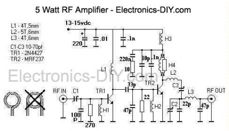
This design is a 2 stage amplifier that has about 17db of gain, suitable for an input of 50 to 100 MW. Its basically a Veronica 5 watt vco transmitter, without the vco. The transistors are a 2N4427 and a MRF237. Output power is 2.5 to 5 watts, depending on input drive and dc voltage. At 13.7 vdc with 50 MW of drive, the output was 2.5 watts. The maximum dc voltage recommended is about 15-16 volts.
The unit is constructed with copper clad board, a large piece is used as the construction surface and is mounted into a case. Other board material is cut into small pads, then glued to the construction surface for part connections. A heatsink is needed for the both transistors, a small top hat style will work for TR1 but TR2 requires a larger heatsink thats attached to the case. This is made from aluminum L stock, a 3/8 hole and a slot is made for TR2 to fit snuggly in. Up to 7-8 watts output is possible with this amp, but for continious duty only 5 watts maximum output is recommended. A fan is required and it is mouted on the case lid, with holes drilled for ventilation. The chokes H1, H2 and H3 are 5 turns of 30 awg wire on a ferite bead and choke H4 is a 330 ohm 1/2 watt resistor with 14 turns of 30 awg with a ferite bead on each end. Ferite beads need to be of type 43 material. The coils L1, L2 and L3 are made of 18 awg tinned wire. A 1.5 amp 3ag fuse is part of the dc power cord assembly. I used BNC coax connectors for input and output, however SO-239 or F type connectors would be fine too. Tune up and use: In order to make the amplifier operate properly, it needs to be tuned. To start, set all the trimmer capacitors to middle position, connect the rf out to a wattmeter/dummy antenna, apply power and drive from the exciter then tune for maximum output. Limit your drive to 100 MW maximum. If you can measure the amplifier transistor's current, then adjust for minimum current at maximum rf out. This unit has no swr protection and requires a 50 ohm antenna, do not operate the amplifier without a proper load.
(View)
View full Circuit Diagram | Comments | Reading(3852)
3W FM Transmitter Amplifier
Published:2012/11/11 20:27:00 Author:muriel | Keyword: 3W , FM Transmitter, Amplifier
View full Circuit Diagram | Comments | Reading(4299)
30Watt VHF Amplifier Circuit for FM Broadcast Band
Published:2012/11/11 20:25:00 Author:muriel | Keyword: 30Watt, VHF , Amplifier Circuit, FM Broadcast Band
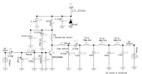
The 30 watt amplifier schematic shown below provides an appropriate power boost with an input of 4 watt up to 6 watts. The circuit is designed to cover 88-108MHz FM Broadcast Band. However, the circuit is very stable at my place and provides a clean-output through seven (7) element Butter-worth low-pass filter.
The heart of the circuit is 2SC1946A VHF RF power transistor. The transistor is specifically designed for operation in frequencies up to 175 MHz, with very good results. As you can see, the power line is well decoupled. The amplifier current can be over 5 amps. All the coils are made from 16gauge laminated wire (or Silver copper wire can do best) and the RFC can be of HF toroid core (as shown in the picture) or 6 holes ferrite bead.C3 and R1 forms snubber circuit while R2 and C6 prevent the amplifier from self-oscillation at VHF, sometimes you need to add 180 ohms in parallel with L7.That will cause the amplifier to dissipate UNDESIRABLE VHF thereby reducing spurious level. The photo below is 60Watts VHF power amplifier using the above circuit. Two of 2SC1946A transistors are arranged at 90 degrees to each other and their outputs are combined using Power Combiner Network�. It is quite difficult to combine powers at VHF and UHF bands. However, I recommend that hobbies should stick to single power design due to its complicity and large rate of INTERFERENCE. (in attempt to go for double transistors which involves power combiner network). Since the two amplifiers are operating in different phase (out of phase). Tuning: Tuning of the amplifier is not hard at all. You just have to connect the output to a good antenna with a transmission line (RG214) of 50 ohms. First match the output network, and then do the same to the input network for a maximum power output. By way of adjustment, you can increase the output at its operating frequency.
(View)
View full Circuit Diagram | Comments | Reading(2264)
30W VHF FM Amplifier for 88 - 108 MHz with BLF245 MOSFET
Published:2012/11/11 20:24:00 Author:muriel | Keyword: 30W, VHF, FM Amplifier, 88 - 108 MHz, BLF245, MOSFET
The achievement of this 30-watt amplifier has been designed to take place on a heatsink microprocessor PC equipped with its fans, the advantage of this method of cooling has been selected for the fact that it is not very common and expensive. The size of the printed circuit will adapt quite easily to the type of heatsink as you have available, if possible, because in many cases, those of recovery, the fans have already lived and the price of a model remains very affordable. (View)
View full Circuit Diagram | Comments | Reading(1838)
30 Watt Linear FM Amp with BLY89
Published:2012/11/11 20:20:00 Author:muriel | Keyword: 30 Watt, Linear, FM Amp, BLY89
A amplifier of medium force RF for the FM, is always essential for the amateur that wants it strengthens some small transmitter, that likely it has already it manufactured! The present circuit can give force 25-30W, with control no bigger than 4-5 W. As it appears in the analytic drawing, the amplifier is manufactured with the transistor TR1 of type LY89 of Phillips. The transistor this is specifically drawn for operation in frequencies up to 175Mhz, with very good results. (View)
View full Circuit Diagram | Comments | Reading(3156)
2W RF Amplifier For 24/23 CM
Published:2012/11/11 20:18:00 Author:muriel | Keyword: 2W , RF Amplifier, 24/23 CM
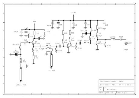
This page describes TX ATV Transmitter for 23 cm with output adjustable from 100 to 250mW. (View)
View full Circuit Diagram | Comments | Reading(2439)
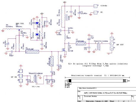
28W FM Broadcast Transmitter Amplifier 88-108 MHz
Published:2012/11/11 20:17:00 Author:muriel | Keyword: 28W, FM, Broadcast , Transmitter, Amplifier, 88-108 MHz
This RF Amplifier designed for FM broadcast using a single 2SC1946 VHF Power Transistor. This 10-30W RF amplifier circuit provides an appropriate power boost with an input of 1-3 watt. Tower are 30 meters high will send signal surrounding air should be around 15 km. The layout of the 2SC1946 28 Watts FM broadcast RF amplifier has been created with Eagle. The pcb outline is 100 x 50 mm (width x height), all bitmaps have a resolution of 600dpi.Use FR-4 single sided photoresist epoxy pcb material for best results. (View)
View full Circuit Diagram | Comments | Reading(2600)
25-W RF amplifier
Published:2012/11/11 20:14:00 Author:muriel | Keyword: 25-W RF amplifier
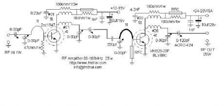
RF amplifier with 25W of power for 88-108MHz FM transmitters. (View)
View full Circuit Diagram | Comments | Reading(2165)
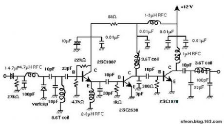
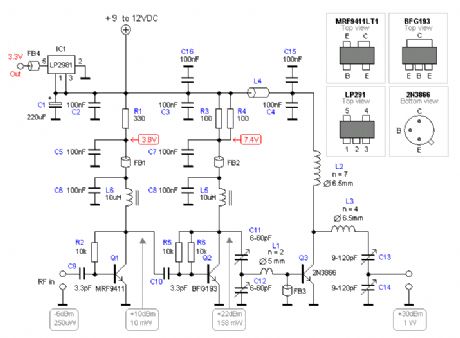
250mW FM Transmitter Amplifier
Published:2012/11/11 20:13:00 Author:muriel | Keyword: 250mW, FM , Transmitter, Amplifier
This project is a simple 2-transistor VHF power amplifier, with about 16dB gain, and requires no tuning or alignment procedures. Wideband techniques have been used in the design and the circuit is equipped with a lowpass filter to ensure good output spectral purity. The project has been designed for assembly on a single-sided printed circuit board. The circuit is specifically designed to amplify the output of 7mW to 10mW WBFM transmitters (wide band) to a final level of 250mW to 300mW.
The first stage (Q1) operates in Class-A. Although Class-A is the least efficient mode, it does offer more RF gain than other clases of bias, and Q1 is a low-level stage, when compared to the higher power Q2 stage. The output of this stage is around 70mW of RF power. The stage is untuned so that it gives a very broadband characteristic. The transistor is biased by means of R5, R6 and L6, and the residual (standing) DC current is set by R4. The input signal is coupled by C9 to the Base of the transistor. Q2 is operated in Class-AB which leads to greater efficiency, but the RF gain is only about 8dB, but it amplifies the output of Q1 to typically 250mW. Q2 is biased by means of R3, R2 and L4. The input signal from Q1 is coupled to the Base of Q2 via C7. The voltage regulator Q3 (78L08) is used to regulate the supply voltage to Q1 and the bias votages to both Q1 and Q2 so that the output RF power is relatively constant, even with large variations of supply voltage. Q3 also removes supply ripple as well as providing power for an FM transmitter like Kit 3018 wireless microphone with the required DC 8v power. The output of the amplifier is filtered with a low-pass filter to reduce the output spurious and harmonic content. The output filter consists of C3, C4, L1 and L2. (View)
View full Circuit Diagram | Comments | Reading(1556)
1W RF Power Amplifier for iPOD Stereo FM transmitters
Published:2012/11/11 20:08:00 Author:muriel | Keyword: 1W, RF , Power Amplifier, iPOD , Stereo , FM transmitters
This project explain how you can build and connect a powerful 1W amplifier to your FM transmitters. A perfect solution for those wishing to listen to their favorite tunes in the car, house, garden, school, campus, party, you name it.... Why not share your music with every one else in your city! (View)
View full Circuit Diagram | Comments | Reading(3240)
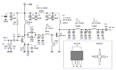
100W Transmitter RF Power Amplifier 2SC2782
Published:2012/11/11 19:57:00 Author:muriel | Keyword: 100W , Transmitter , RF, Power Amplifier, 2SC2782
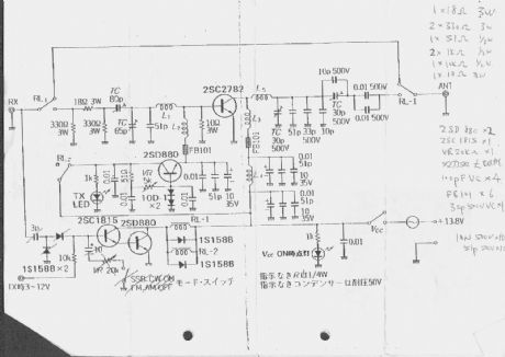
This is a 6m band transmitter RF power amplifier (50 MHz) with 100W output. It used with my FT-736R and drive from 10W for the 6m SSB DX. The Building information comes from Japan CQ Magazine. The Toshiba RF bipolar power transistor is used in it. If you want to construct this rf amplifier, it's the better way if the double side PCB use for increase the grounding and current transfer. The TX power can be tune to 120W. (View)
View full Circuit Diagram | Comments | Reading(3704)
100W Transmitter Amplifier for 2200m
Published:2012/11/11 19:56:00 Author:muriel | Keyword: 100W , Transmitter, Amplifier, 2200m
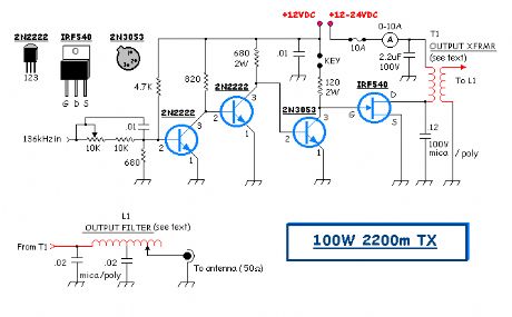
This particular transmitter was later shipped up to VY1JA in the Yukon where, thanks to Jay's excellent antenna system, it was heard in Europe as well as in New Zealand during one of the Trans-Pacific Tests! Running 24 volts on the final will produce 100 watts into a 50 ohm load. The transmitter utilizes a 4060 binary counter IC chip as both the crystal oscillator and frequency divider. I used a 2200 kHz crystal along with the 'divide-by' sixteen output to produce a signal at 137.5 kHz. Other combinations of crystal frequencies and 'divide-by' combinations may also be used since the 4060 features divided outputs for f/32 (pin 5) and f/64 (pin 4), among others. You may have a 4MHz crystal or an 8MHz crystal in your junk box that will put you in the band using these output pins.
I used a crystal oven from a very old taxi cab fm radio to mount the crystal but do not use the 'oven' feature. I discovered that the thermostat-controlled heating / cooling cycle produced more drift than simply leaving the oven off. I have however, lined both the inside and the outside of the oven with styrofoam in hopes of keeping the crystal's temperature change to a minimum. Initial tests indicate that it is entirely adequate for QRSS30 speeds. I have not yet tested it at QRSS60, where even the slightest drift shows up very quickly. The transmitter is simple and inexpensive to construct. The IRF540 FET final runs very cool, although it should probably be heat sinked. I have also used IRF640s with little or no change noted. All coils and transformers are wound on ABS or PVC tubing. TRANSMITTER SCHEMATIC I used the Manhattan Style of construction on pc board. TRANSMITTER PCB Output Transformer (T1) - wound on 1.5 tubing ~ 5 inches in length. Wind the secondary first which consists of 80 turns of ~ #20 enamel wire. Wind the primary centered on top of the secondary with 15 turns of ~ #16 enamel, close spaced. Before winding the primary, wrap the center part of the secondary with PVC electrical tape or heavy plumber's teflon tape. Output Filter (L1) - wound on 2 tubing ~ 5 inches in length. Wrap 80 turns of #20, close spaced with taps at 40 turns and every 5 turns until the end. The capacitor used at the drain of the FET should be of high quality such as polycarbonate or mica. Although the original design indicated a 1 uF capacitor at the top end of T1's primary, I found that the 2.2uf gave a better waveform across the FET's drain. Look for the typical class-e type waveform at the drain. CLASS-E WAVEFORM Operation - Mitch's version of this amp appears to be operating at greater efficiency than the one I built. Running the final at 24VDC, the FET draws around 6.5-7 amps for an input of approximately 160W. With a measured output of 95W, the efficiency is around 60%. A properly designed class-e amplifier should realize much higher efficiencies so there is still plenty of room for improvement on this design. One of the things I would like to do is experiment with the output transformer in order to optimize its performance. Perhaps rewinding it on a ferrite core would help. The output transformer develops a lot of heat, indicating a substantial power waste. Perhaps that is where the missing 30% efficiency can be reclaimed. Operate the transmitter into a 50 ohm dummy load or your resonant (50 ohm) antenna system. You might want to 'tune-up' at a lower voltage and then increase the drain voltage when adjustments are completed. Start with the antenna tapped at the coaxial end of the filter coil. As you tap closer to the center, power output will increase, as will final amplifier drain current. You will reach a point where the output does not increase any further, even though drain current has increased. Tap at the point of best efficiency. The output waveform should be a clean sine-wave. (View)
View full Circuit Diagram | Comments | Reading(3405)
1.5W VHF Amplifier
Published:2012/11/9 21:05:00 Author:muriel | Keyword: 1.5W , VHF Amplifier
This project will explain the basic function of a class-C transmitter. I will explain how to dimension a transmitter and the purpose of the different components. I will also explain how you can build a 1.5W PA transmitter. The project will include PCB, components and instructions how to make coils, assembly and testing. (View)
View full Circuit Diagram | Comments | Reading(3476)
1.3W VHF RF Amplifier 2SC1970 88-108 MHz
Published:2012/11/9 21:01:00 Author:muriel | Keyword: 1.3W, VHF, RF Amplifier, 2SC1970, 88-108 MHz
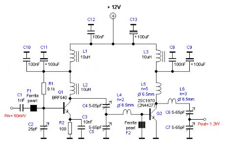
This RF power amplifier is based on the transistor 2SC1970 and 2N4427. The output power is about 1.3W and the input driving power is 30-50mW. It will still get your RF signal quit far and I advice you to use a good 50 ohm resistor as dummy load. To tune this amplifier you can either use a power meter/wattmeter, SWR unit or you can do using a RF field meter.
RF Amplifier Assembly Good grounding is very important in a RF system. I use bottom layer as Ground and I connect it with the top with wires to get a good grounding. Make sure you have some cooling at the transistor. In my case I put the 2SC1970 close to the PCB to handle the heat. With good tuning the transistor shouldn't become hot. RF Amplifier Printed Circuit Board You can download a pdf file which is the black PCB. The PCB is mirrored because the printed side side should be faced down the board during UV exposure. To the right you will find a pic showing the assembly of all components on the same board. This is how the real board should look when you are going to solder the components. It is a board made for surface mounted components, so the copper is on the top layer. I am sure you can still use hole mounted components as well. Grey area is copper and each component is draw in different colors all to make it easy to identify for you. The scale of the pdf is 1:1 and the picture at right is magnified with 4 times. Click on the pic to enlarge it. Low-Pass Filter Some of you might want to add a low-pass filter at the output. I have not added any extra low pass filter in my construction because I don't think it is needed. You can easy find several homepages about low pass filter and how to build them.
(View)
View full Circuit Diagram | Comments | Reading(2973)
| Pages:38/250 At 202122232425262728293031323334353637383940Under 20 |
Circuit Categories
power supply circuit
Amplifier Circuit
Basic Circuit
LED and Light Circuit
Sensor Circuit
Signal Processing
Electrical Equipment Circuit
Control Circuit
Remote Control Circuit
A/D-D/A Converter Circuit
Audio Circuit
Measuring and Test Circuit
Communication Circuit
Computer-Related Circuit
555 Circuit
Automotive Circuit
Repairing Circuit