
Amplifier Circuit
Index 41
100MHz Op Amp LT6203
Published:2012/10/18 3:30:00 Author:muriel | Keyword: 100MHz, Op Amp, LT6203
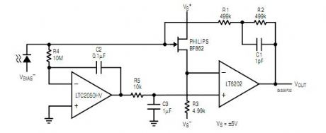

In this case however, the JFET is not allowed to dictate the DC bias conditions. Instead of simply grounding the LT6202 noninverting input, an LTC2050 drives it (and therefore the source) exactly to where it needs to be for zero JFET gate voltage. The addition of the LTC2050 increases the total supply current by about 1mA. (View)
View full Circuit Diagram | Comments | Reading(1399)
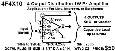
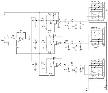
4-output distribution 1W pk amplifier
Published:2012/10/18 3:28:00 Author:muriel | Keyword: 4-output, distribution, 1W, pk amplifier
View full Circuit Diagram | Comments | Reading(1003)
Miniature Audio Oscillator
Published:2012/10/18 3:16:00 Author:muriel | Keyword: Miniature , Audio, Oscillator
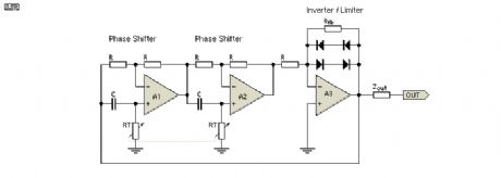
The oscillator circuit (see Figure 1) involves two unity gain phase shift stages, A1 and A2, in tandem and a gain stage, A3, with back to back diodes and resistor network providing non-linear negative feedback. At a particular frequency (determined by RT and CT - the timing components) A1 and A2 provide 90 degrees phase shift each, 180 degrees in total and the circuit begins oscillating, since A3 and its non linear network has more than unity gain for small signals. As the oscillation level increases the diodes conduct and limit the gain of A3 stabilising the output at the desired level, in this case a little over 1V RMS. However, some distortion of the sine wave peaks is caused by the diodes. (View)
View full Circuit Diagram | Comments | Reading(1291)
Microphone Mixer
Published:2012/10/18 3:15:00 Author:muriel | Keyword: Microphone, Mixer
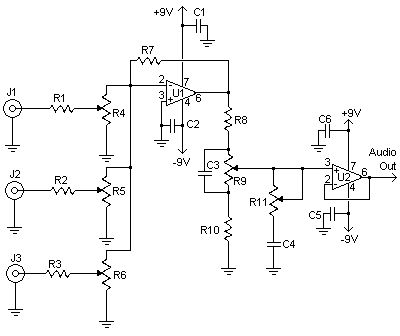
This relatively simple mixer was designed for three dynamic microphones, but can be re-designed for more or less. Level and tone controls are available to tailor the sound to your needs.
(View)
View full Circuit Diagram | Comments | Reading(2851)
Simple line mixer
Published:2012/10/18 3:14:00 Author:muriel | Keyword: Simple line, mixer

I designed this circuit for one friend of mine to be used as a small portable DJ mixer. The circuit is an audio mixer circuit so simple as it can be. There are two dual logarithmic potentiometers in the circuit to adjust the input signal levels and some resistors to do the actual mixing. The circuit is totally passive, so no power supply is needed.
The circuit is suitable to be uses as a mixer between two line level sources and one HIFI amplifier input. This circuit have been successfully used for mixing signals form two CD players or computer soundcard and CD players. There are many situations where simple mixer would be useful and commercially available mixer desks are too expensive and big.
This simple line mixer has two drawbacks: it attenuates the signal all the time (even sliders set to maximum) and the output impedance is quite high. The first problem can be solved by just turning a little more volume in the amplifier. High ouput impedance is no problem when connected to high impedance amplifier input with short wires (few meters).
In the picture below you see the schematic of the whole mixer circuit. The potentiometer slides which are actually inside one dual potentiometers are connected together using one line. Every input and output pin has corresponding ground signal on the right side of the signal line.
(View)
View full Circuit Diagram | Comments | Reading(1311)
FET Audio Mixer
Published:2012/10/18 2:29:00 Author:muriel | Keyword: FET, Audio, Mixer
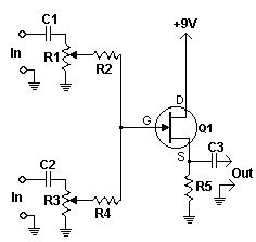
This simple circuit mixes two or more channels into one channel (eg. stereo into mono). The circuit can mix as many or as few channels as you like and consumes very little power. The mixer is shown with two inputs, but you can add as many as you want by just duplicating the sections which are clearly visible on the schematic.
(View)
View full Circuit Diagram | Comments | Reading(1488)
Simplest Ever Amplifier Bridging
Published:2012/10/18 2:28:00 Author:muriel | Keyword: Simplest Ever, Amplifier

In another of my project pages, there is a design for a simple add-on bridging adapter for stereo power amplifiers. There is, however, an even simpler way, provided you have (or can trace out) the appropriate section of the amplifier circuit.
Nearly all modern amplifiers use a long-tailed pair as the input and error amplifier (the error amp is the LTP, which detects any variation between its inputs - an error voltage - and corrects it). The input is connected to the base of one of the LTP transistors, and the feedback to the other. The feedback signal is attenuated by the network, by an amount equal to the gain of the amplifier.
By connecting the output of one amplifier to the feedback point in the other, using a resistance equal to that for the feedback resistor, the second amp will have a signal gain of unity, and will be inverted, since the feedback is always applied to the inverting input. (View)
View full Circuit Diagram | Comments | Reading(1803)
Low Frequency Wien Bridge RC Sinewave Oscillators
Published:2012/10/18 2:08:00 Author:muriel | Keyword: Low Frequency, Wien Bridge , RC Sinewave , Oscillators
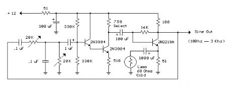

Three examples of Wien Bridge oscillators are shown below. The first uses three bipolar transistors. The second uses a bipolar and JFET, and the third is the more popular type using an op-amp for minimal parts. The idea is to generate a 360 degree phase shift at some particular frequency using 2 resistors and caps of equal value. One cap and resistor are in series, while another cap and resistor are in parallel. The signal loss through the network is about 66 percent so the amplifier gain needs to be around 3 for a loop gain of 1. The gain of the amplifier is critical since too much gain will produce a clipped (distorted) waveform and not enough gain will not sustain oscillation. This is almost impossible to achieve without some automatic gain control (AGC) to regulate the gain and produce stable operation. The usual AGC is accomplished with a small light bulb where resistance increases as the signal level rises and reduces the gain. The lamp used here is a 1819 (28 volt 40mA) variety found at Radio Shack, part number 272-1119. Another lamp that might be useful is the GE394, 12 volt 40mA, but a little harder to find.
In the first example, the lamp is placed in series with a 1000uF cap and connected across the emitter resistor of the 2N2219A so as the signal level rises, the total resistance increases reducing the gain. The gain of the 2N2219A stage is approximately the collector resistor (100) divided by the emitter resistor (51 in parallel with the lamp 75) or maybe 100/30 = 3.3, The first stage (2N3904 on the left) provides a high impedance to the RC network so it doesn't load down the input much. The second stage (2N3904) in the middle, provides a 180 degree phase inversion and not much voltage gain. So, the overall phase shift is 360 degrees, 180 from the middle stage and another 180 from the 2N2219A stage. The overall gain can be adjusted with the 750 ohm resistor at the collector of the center stage. The example shows 2 (20K) variable resistors which are ganged together for frequency adjustment of about 10KHz to 400 Khz. Lower frequencies can be obtained using larger capacitors. The frequency of oscillation is f = 1/(2 * Pi * R * C). The circuit was built sucessfully and also simulated using LTSpice version IV. A copy of LTSpice can be downloaded from the following link. (View)
View full Circuit Diagram | Comments | Reading(2366)
LM324 op-amp
Published:2012/10/17 22:22:00 Author:muriel | Keyword: LM324, op-amp
View full Circuit Diagram | Comments | Reading(5043)
Bidirectional line driver circuit composed of double broadband transconductance operational amplifier OPA2662
Published:2012/10/15 21:42:00 Author:Ecco | Keyword: Bidirectional , line driver , double broadband , transconductance , operational amplifier
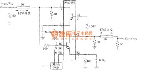
The circuit uses OPA2662 internal dual OTA to form two - channel current output drive circuit, and one channel is used as send driver, the other way is used as receiver driver, sending and receiving switch is controlled by the enable terminal EN. When 3 feet (EN1) is high ( 6 feet EN2 is low at this time), the circuit is in the receiving state, the input signal is sent into 2 feet by cable, then it is amplified and output from 14 feet.
(View)
View full Circuit Diagram | Comments | Reading(1528)
LOG101/104 precision logarithmic and logarithmic ratio amplifier
Published:2012/10/15 22:46:00 Author:Ecco | Keyword: precision logarithmic, logarithmic ratio, amplifier

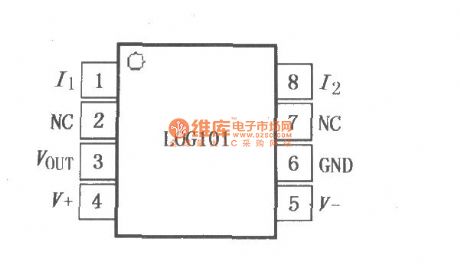
In logarithmic ratio computing applications, a signal current can be from the photodiode, and another reference current is derived from a series resistor of external precision reference. The VOUT terminal's output signal is tuned with the input current decimal 1V, and it allows seven decimal input current dynamic range. LOG101/104 has a low DC offset voltage and low temperature drift characteristics, and it can be used for the measurement of low-level signal in a wide ambient temperature.
(View)
View full Circuit Diagram | Comments | Reading(1332)
50-Watt Amplifier
Published:2012/10/12 22:53:00 Author:muriel | Keyword: 50-Watt, Amplifier

This is a handy, easy to build general purpose 50 watt amp. The amp has an input for a radio, TV, stereo or other line level device. It also has a phono input for a record player, guitar, microphone or other un-amplified source. With the addition of a low pass filter at the input, it makes a great amp for a small subwoofer. (View)
View full Circuit Diagram | Comments | Reading(1566)
5 Watt Class-A Audio Amplifier
Published:2012/10/12 22:52:00 Author:muriel | Keyword: 5 Watt , Class-A, Audio Amplifier
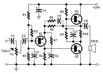
In the old valve days, most commercial audio amplifiers suited for compact integrated mono or stereo record players used a one-valve amplifier topology. The circuit was usually implemented by means of a multiple type valve, e.g. a triode pentode ECL86. Common features for those amplifiers were: Class A operation, output power in the 3 - 5W range, input sensitivity of about 600mV for full output power, THD of about 3% @ 3W and 1KHz. Best types showed THD figures of 1.8% @ 3W and 0.8% @ 2W. This solid-state push-pull single-ended Class A circuit is capable of providing a sound comparable to those valve amplifiers, delivering more output power (6.9W measured across a 8 Ohm loudspeaker cabinet load), less THD, higher input sensitivity and better linearity. (View)
View full Circuit Diagram | Comments | Reading(2455)
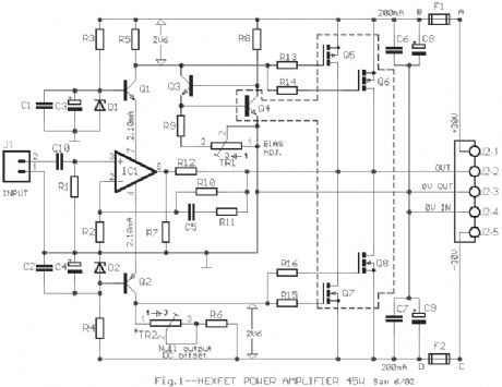
45W HEXFET Power Amplifier
Published:2012/10/12 22:51:00 Author:muriel | Keyword: 45W , HEXFET , Power Amplifier
View full Circuit Diagram | Comments | Reading(1222)
3 Band Equalizer
Published:2012/10/12 22:50:00 Author:muriel | Keyword: 3 Band, Equalizer
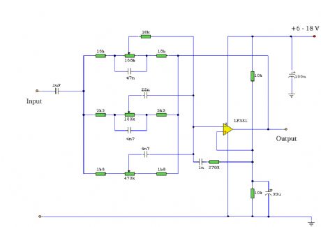
A tone control circuit made with a single op-amp and having three ranges, bass, middle and treble controls.
Notes:Using a single op-amp this easy to make equalizer offers three ranges, low frequency,mid frequency,and high. With component values shown there is approximately +/-20dB of boost or cut at frequencies of 50Hz, 1kHz and 10kHz. Supply voltage may be anything from 6 to 30 Volts. Maximum boost 20dB is only realized with maximum supply voltage of 18 Volt. (View)
View full Circuit Diagram | Comments | Reading(3581)
A 32 Watt per channel stereo power amplifier
Published:2012/10/12 22:49:00 Author:muriel | Keyword: 32 Watt, per channel , stereo , power amplifier
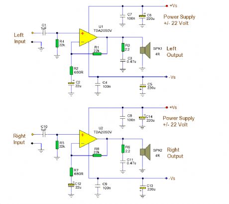
A 32 Watt per channel stereo power amplifier made using the TDA2050V monolithic integrated circuit. NotesThis circuit is for a 32 Watt stereo audio power amplifier using the TDA20501. With a dual 22 Volt supply this amplifier can deliver 32W into 8 ohm loudspeakers. Moreover, the TDA 2050 delivers typically 50W music power into 4 ohm load over 1 sec at VS= 22.5V and f = 1KHz.
This is a power amplifier and requires 200mV RMS for full output. Voltage gain is 30.5dB with resistor values shown. Closed loop gain is set by Ratio R1/R2. Increase R2 for less gain and vice versa. Power bandwidth is 20Hz to 80KHz. R3, C3 and R6, C11 form a zobel network to prevent high frequency instability.The speaker is direct coupled, therefore no expensive large value electrolytics are needed and the bass will be crisp and clean. It is advisable to place fuses in the power supply (not shown). (View)
View full Circuit Diagram | Comments | Reading(2227)
30-W MosFet Audio Amplifier
Published:2012/10/12 22:48:00 Author:muriel | Keyword: 30-W, MosFet, Audio Amplifier
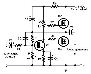
This project was a sort of challenge: designing an audio amplifier capable of delivering a decent output power with a minimum parts count, without sacrificing quality. The Power Amplifier section employs only three transistors and a handful of resistors and capacitors in a shunt feedback configuration but can deliver more than 18W into 8 Ohm with <0.08% THD @ 1KHz at the onset of clipping (0.04% @ 1W - 1KHz and 0.02% @ 1W - 10KHz) and up to 30W into a 4 Ohm load.
(View)
View full Circuit Diagram | Comments | Reading(1953)
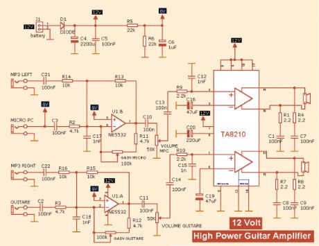
30w + 30w GUITAR AMPLIFIER
Published:2012/10/12 22:46:00 Author:muriel | Keyword: 30w + 30w, GUITAR AMPLIFIER
View full Circuit Diagram | Comments | Reading(1390)
300 Watt MOSFET HI-FI Power Amplifier
Published:2012/10/12 22:45:00 Author:muriel | Keyword: 300 Watt, MOSFET, HI-FI, Power Amplifier
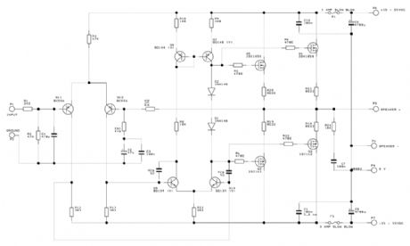
The amplifier consists of two completely separate monaural amplifiers each channel has its own power supply, resulting in zero inter-channel cross talk, a common phenomenon in amplifiers sharing the same power supply. In order to obtain the full output power each supply transformer should be rated at 40VAC - 0 - 40VAC at 640VA. Unlike many designs relying on the reservoir capacitors to supply peak currents, I prefer to have the raw power available from the transformer resulting in much faster transients.
Although the RAS 300 specifications are moderate, when listening to it you will immediately experience the massive reserve power available and never have any cause of anxiety that something is going to give in that one would when driving many amplifiers loud. You will hear nothing but reality with no distortion at any level and I guarantee that this amplifier will divulge the best qualities of any equipment connected to it.
(View)
View full Circuit Diagram | Comments | Reading(2851)
3 Channel Spectrum Analyzer
Published:2012/10/12 22:44:00 Author:muriel | Keyword: 3 Channel, Spectrum Analyzer
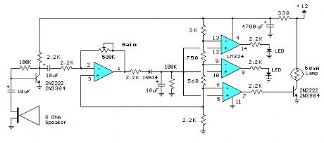
This 3 channel 15 LED spectrum analyzer is the perfect addition to any audio amp project. It produces fantastic displays on three LED bars that can be individually adjusted for any particular frequency range. The circuit will take line level output from most any audio source, and operates on 12V DC. This means that it can even be run in a car. (View)
View full Circuit Diagram | Comments | Reading(1461)
| Pages:41/250 At 204142434445464748495051525354555657585960Under 20 |
Circuit Categories
power supply circuit
Amplifier Circuit
Basic Circuit
LED and Light Circuit
Sensor Circuit
Signal Processing
Electrical Equipment Circuit
Control Circuit
Remote Control Circuit
A/D-D/A Converter Circuit
Audio Circuit
Measuring and Test Circuit
Communication Circuit
Computer-Related Circuit
555 Circuit
Automotive Circuit
Repairing Circuit