
Amplifier Circuit
Index 53
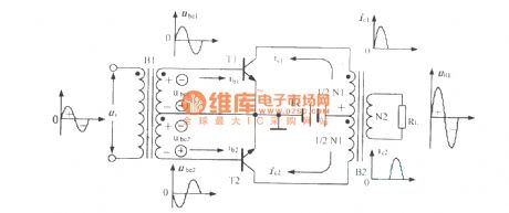
Carrier isolation amplifier circuit
Published:2011/12/2 1:49:00 Author:Ecco | Keyword: Carrier, isolation amplifier
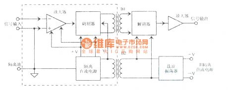
View full Circuit Diagram | Comments | Reading(878)
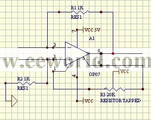
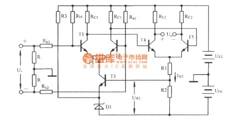
The directly coupled amplifier
Published:2011/12/2 1:50:00 Author:Ecco | Keyword: directly, coupled amplifier
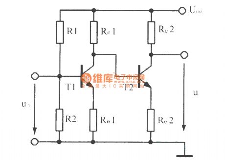
View full Circuit Diagram | Comments | Reading(973)
3310 changing into 600 power amplifier diagram
Published:2011/11/4 3:12:00 Author:Ecco | Keyword: power amplifier
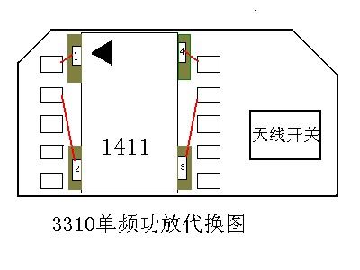
3310 monofrequent power amplifier substitution chart
(View)
View full Circuit Diagram | Comments | Reading(808)
3508 changing into 600 power amplifier diagram
Published:2011/11/4 3:12:00 Author:Ecco | Keyword: power amplifier
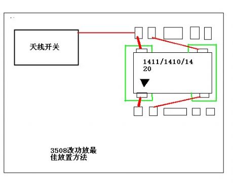
View full Circuit Diagram | Comments | Reading(666)
The power amplifier diagram of 600 changing into 3508
Published:2011/11/10 3:28:00 Author:Ecco | Keyword: power amplifier
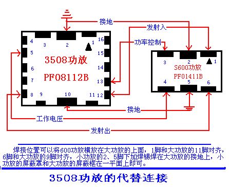
The 600 power amplifier's welding position can be placed across the top of the power amplifier, the pin 1 of small power amplifier and and pin 11 of large power amplifer are put in alignment, pin 6 of small power amplifier and and pin 9 of big power amplifer are put in alignment, and small power amplifier's pin 2,5 are welding and grounded, and the small amplifier's shield and the large power amplifier's shielding box can be on a plane.
(View)
View full Circuit Diagram | Comments | Reading(785)
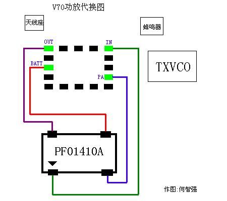
V70 power amplifier substitution chart
Published:2011/11/4 3:07:00 Author:Ecco | Keyword: power amplifier, substitution chart
View full Circuit Diagram | Comments | Reading(770)
V66V60 power amplifier chart
Published:2011/11/4 3:09:00 Author:Ecco | Keyword: power amplifier
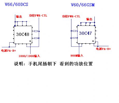
When thetail of phonefaces down,the power amplifier position can be seen.
(View)
View full Circuit Diagram | Comments | Reading(688)
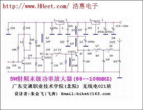
5W RF final stage amplifier
Published:2011/11/11 2:13:00 Author:Ecco | Keyword: 5W , RF , final stage , amplifier
View full Circuit Diagram | Comments | Reading(1536)
Key pin features LM378 audio amplifier
Published:2011/11/4 3:00:00 Author:Ecco | Keyword: Key pin features , audio amplifier
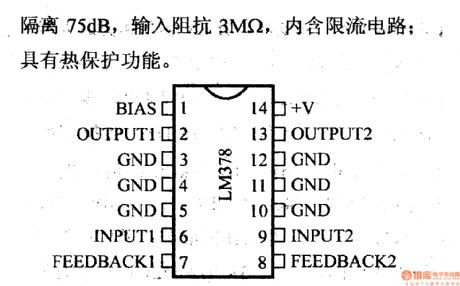
The monolithic double power amplifier can be connected to 8Ω or 16Ω load to make each channel output 4W. The ripple suppresses is 70dB; the channel isolation is 75dB, and the input impedance 3MΩ, and it contains current limiting circuit; it has the heating protection function.
(View)
View full Circuit Diagram | Comments | Reading(2147)
The integrated infrared receiver circuit with pre- amplifier
Published:2011/11/7 21:13:00 Author:Ecco | Keyword: integrated infrared receiver, pre- amplifier
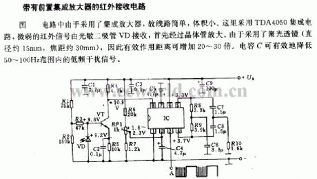
In the circuit, it uses the integrated amplifier, so the circuit is simple with small size. It uses the TDA4050 IC, and the weak infrared signal is received by the photosensitive diode VD,then it is amplified by transistor. As a result of the condenser lens ( diameter is about 15mm, focal length is about 30mm), it can increase the effective distance with 20 to 30 times. Capacitor C can effectively reduce the range of 50 ~ 100Hz low-frequency interference signals.
(View)
View full Circuit Diagram | Comments | Reading(1619)
Key pin features of IR3F02 operational amplifier
Published:2011/11/4 3:05:00 Author:Ecco | Keyword: Key pin features , operational amplifier
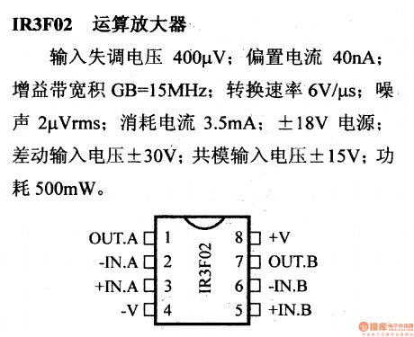
Input offset voltage is 400μV; Bias current is 40nA; Gain-bandwidth product GB=15MHz; Switching rate is 6V/μS; Noise is 2μVms; Current consumption is 3.5mA; it uses ±18V power source; Differential motion input voltage is ±30V; Syntype input voltage is ±15V; Power loss is 500mW.
(View)
View full Circuit Diagram | Comments | Reading(1424)
Dynamic audio preamplifier
Published:2011/11/7 20:51:00 Author:Ecco | Keyword: Dynamic audio preamplifier
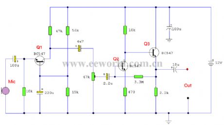
This is a 3 stage discrete amplifier with gain control. Alternative transistors such as BC109C, BC548, BC549, BC549C may be used with little change in performance. The first stage built around Q1 operates in common base configuration. This is unusuable in audio stages, but in this case, it allows Q1 to operate at low noise levels and improves overall signal to noise ratio. Q2 and Q3 form a direct coupled amplifier, similar to my earlier mic preamp.Input and Output Impedance:As the signal from a dynamic microphone is low typically much less than 10mV, then there is little to be gained by setting the collector voltage voltage of Q1 to half the supply voltage. In power amplifiers, biasing to half the supply voltage allows for maximum voltage swing, and highest overload margin, but where input levels are low, any value in the linear part of the operating characteristics will suffice. Here Q1 operates with a collector voltage of 2.4V and a low collector current of around 200uA. This low collector current ensures low noise performance and also raises the input impedance of the stage to around 400 ohms. This is a good match for any dynamic microphone having an impedances between 200 and 600 ohms. (View)
View full Circuit Diagram | Comments | Reading(1249)
The reference for amplifier circuit
Published:2011/11/7 20:53:00 Author:Ecco | Keyword: amplifier circuit
View full Circuit Diagram | Comments | Reading(827)
Quadraphonic Amplifier
Published:2011/11/7 21:40:00 Author:Ecco | Keyword: Quadraphonic Amplifier
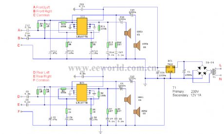
This is a four channel amplifier ideally suited for use with quadraphonic equipment such as a Sound Blaster Live card. There is no volume control,audio levels being directly controlled from the sound card itself.
Parts List:D1-D4: 1N4001 (4)C1,C20: 1000u CAP (2)C2,C11: 47u CAP (2)C3,C5,C7,C8,C12,C14,C16,C17,C21,C22: 0.1u CAP (10)C4,C6,C13,C15: 10u CAP (4)C9,C10,C18,C19: 2200u CAP (4)R1,R4,R9,R12: 1M RESISTOR (4)R2,R6,R10,R14: 100k RESISTOR (4)R3,R5,R11,R13: 1k RESISTOR (4)R7,R8,R15,R16: 2R7 RESISTOR (4)IC1: 7812 (1)IC2,IC3: LM1778N (2)SPK1,SPK2,SPK3,SPK4: 8R 2 Watt speakers (4) (View)
View full Circuit Diagram | Comments | Reading(1138)
Zoom shaping divider circuit
Published:2011/11/7 20:52:00 Author:Ecco | Keyword: Zoom shaping divider
View full Circuit Diagram | Comments | Reading(814)
5.1c power amplifier system
Published:2011/11/4 3:14:00 Author:Ecco | Keyword: power amplifier system
View full Circuit Diagram | Comments | Reading(3694)
Push-pull power amplifier circuit
Published:2011/11/1 21:20:00 Author:Ecco | Keyword: Push-pull, power amplifier
View full Circuit Diagram | Comments | Reading(1094)
Two-level differential amplifier circuit
Published:2011/11/1 21:19:00 Author:Ecco | Keyword: Two-level , differential amplifier
View full Circuit Diagram | Comments | Reading(781)
Temperature sensor isolation amplifier circuit
Published:2011/11/1 21:33:00 Author:Ecco | Keyword: Temperature sensor, isolation amplifier
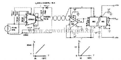
View full Circuit Diagram | Comments | Reading(900)
The driver circuit diagram with 24 LEDs
Published:2011/11/1 21:37:00 Author:Ecco | Keyword: driver , 24 LEDs
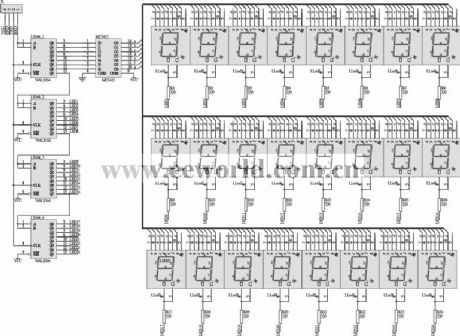
View full Circuit Diagram | Comments | Reading(876)
| Pages:53/250 At 204142434445464748495051525354555657585960Under 20 |
Circuit Categories
power supply circuit
Amplifier Circuit
Basic Circuit
LED and Light Circuit
Sensor Circuit
Signal Processing
Electrical Equipment Circuit
Control Circuit
Remote Control Circuit
A/D-D/A Converter Circuit
Audio Circuit
Measuring and Test Circuit
Communication Circuit
Computer-Related Circuit
555 Circuit
Automotive Circuit
Repairing Circuit