
Amplifier Circuit
Index 42
Amplifier 2x30W with STK465
Published:2012/10/12 22:43:00 Author:muriel | Keyword: Amplifier, 2x30W, STK465
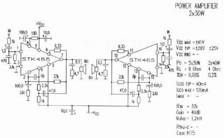
A amplifier of acoustic frequencies can be manufactured with discernible materials, despite is known so much the difficulties of finding of materials, what the problem of regulations. These difficulties are overcome relatively easily if we find amplifier in form completed.
Completed STK465 is an amplifier of acoustic frequencies that offers qualitative output, using minimal exterior elements. Substantially he is one of big completed force. Has a line pins and incorporated metal surface for adaptation in cooler. The provision pins in a line, facilitates the placement completed in the end printed and his support in cooler. The circuit functions in a big range of benefits of catering, from 20V as 60V, and it attributes 30WRMS, when the tendency of catering is above 50V and composer resistance of loudspeaker is the 4 or 8 Ohm. The catering should be symmetrically.
When it functions with tendency 56V then the tendency will be ± 28V as for the ground. With this recommended tendency of catering, the attributed force is 30 WRMS in charge 8W. The price of deformity is acceptable and oscillates around in the 0,08% for force of expense from 1W until 30W. Curve response his it is extended from 10Hz and reaches 100 KHz, with divergence 0dB and -3dB respectively, measured in force 1W. Using evolved techniques, completed amplifier STK465, can minimise the deformities even in highest levels of force. Other characteristically that determines the completed circuit they are: the wide area and the high aid.
(View)
View full Circuit Diagram | Comments | Reading(970)
two transistor operation
Published:2012/10/12 22:42:00 Author:muriel | Keyword: two transistor
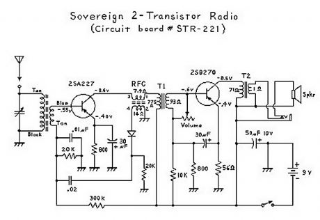
It has been interesting analyzing these radios. You have to give the Japanese credit for even making a radio that can drive a speaker with only 2 transistors! Basically, the first transistor (Q1) performs double-duty. It first acts as an RF amplifier, with some of the signal being fed back to the antenna coil to provide some regeneration for better selectivity and sensitivity. (This also results in a non-linear amplification of the signal which results in noticeable distortion.) The RF (radio frequency) signal is then rectified ( detected ) by the diode, and then the resultant audio signal is fed back to the base of the first transistor where it acts as the first AF (audio frequency) amplifier. (This is called a reflex circuit.) The audio signal is then fed through an interstage transformer to Q2 (the second transistor). The transformer provides impedance matching. The second transistor acts as a power amplifier, with the output signal going through an audio output transformer (to provide impedance matching again), and then finally to the speaker. Everything about this circuit is designed to provide maximimum gain; consequently there is no AGC (automatic gain control), and stronger stations come in a lot louder than weaker stations; unlike 6-transistor (or more) radio circuits which have an AGC circuit or function. (View)
View full Circuit Diagram | Comments | Reading(2026)
2N3055 Power Amplifier
Published:2012/10/12 22:41:00 Author:muriel | Keyword: 2N3055, Power Amplifier
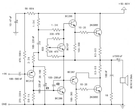
Simple and low cost. The optimal supply voltage is around 50V, but this amp work from 30 to 60V. The maximal input voltage is around 0.8 - 1V. As you can see, in this design the components have a big tolerance, so you can build it almost of the components, which you find at home. The and transistors can be any NPN type power transistor, but do not use Darlington types... The output power is around 60W. (View)
View full Circuit Diagram | Comments | Reading(2579)
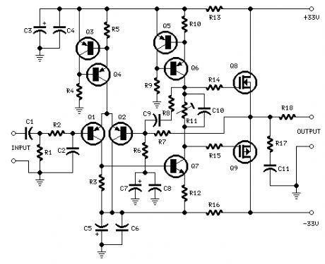
25W Mosfet audio amplifier
Published:2012/10/12 22:40:00 Author:muriel | Keyword: 25W, Mosfet, audio amplifier
View full Circuit Diagram | Comments | Reading(1168)
21W Class AB amplifier
Published:2012/10/12 22:37:00 Author:muriel | Keyword: 21W, Class AB, amplifier

This is an instrument amplifier for monitoring music when on stage. It provides 21W output power of this little design. Previously I had a decent 10W amplifier (RED Free Circuits), but we blew that one somehow. Now I will put this into the old box. I haven't built it yet, but the simulations say it works as I designed. In this design, wiring is important due to no differential amplifier. I might need to add ripple rejection with a zener as in the above design.
(View)
View full Circuit Diagram | Comments | Reading(1972)
20W Bridge Audio Amplifier
Published:2012/10/12 22:35:00 Author:muriel | Keyword: 20W, Bridge, Audio Amplifier
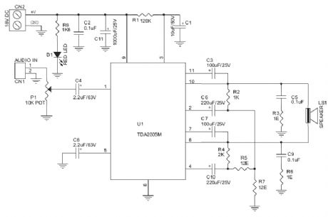
20W Bridge Audio Amplifier kit, based on the TDA2005 IC, a class B dual audio amplifier, specifically designed for car radio applications etc.
Power supply - 18 VDC
Output power - 20 W, 4 Ω
IC built in Thermal Shut-down, Load dump voltage surge protected
Terminal pins for connecting left and right audio signal inputs
Relimate Connector for connecting Potentiometer (POT) for volume adjustment
Power Battery Terminal (PBT) for easy power supply and speaker connection
Power-On LED indicator
Heatsink for IC
Four mounting holes of 3.2 mm each with nut and stud
PCB dimensions 63 mm x 65 mm (View)
View full Circuit Diagram | Comments | Reading(1805)
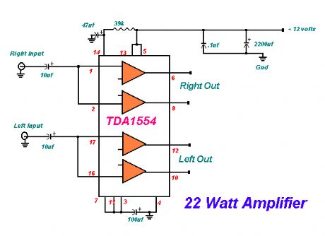
22 Watt Stereo Amplifier
Published:2012/10/12 22:34:00 Author:muriel | Keyword: 22 Watt, Stereo Amplifier
View full Circuit Diagram | Comments | Reading(942)
22 Watt Audio Amplifier
Published:2012/10/12 22:33:00 Author:muriel | Keyword: 22 Watt, Audio Amplifier
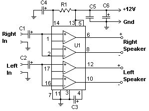
The 22 watt amp is easy to build, and very inexpensive. The circuit can be used as a booster in a car audio system, an amp for satellite speakers in a surround sound or home theater system, or as an amp for computer speakers. The circuit is quite compact and uses only about 60 watts. The circuit is not mine, it came from Popular Electronics.
(View)
View full Circuit Diagram | Comments | Reading(1306)
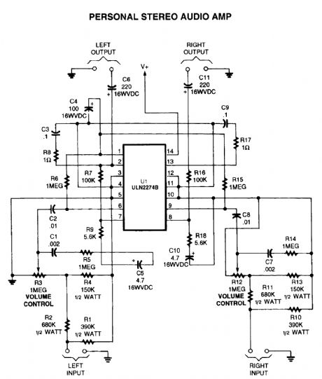
personal stereo audio amplifier
Published:2012/10/12 22:32:00 Author:muriel | Keyword: personal, stereo, audio amplifier
View full Circuit Diagram | Comments | Reading(2016)
2 Watt audio amplifier made from discrete components.
Published:2012/10/12 22:31:00 Author:muriel | Keyword: 2 Watt, audio amplifier
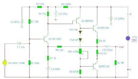
This was one of the earliest circuits that I ever designed and built, in Spring 1982. At that time I had only an analogue meter and a calculator to work with. Although not perfect, this amplifier does have a wide frequency response, low harmonic distortion about 3%, and is capable of driving an 8 ohm speaker to output levels of around 5 watts with slightly higher distortion. Any power supply in the range 12 to 18 Volts DC may be used. The amplifier operates in Class AB mode; the single 470R preset resistor, PR1 controls the quiescent current flowing through the BD139/140 complimentary output transistors. Adjustment here, is a trade-off between low distortion and low quiescent current. Typically, under quiescent conditions, current is about 15 mA rising to 150 mA with a 50 mV input signal. The frequency response is shown below and is flat from 20Hz to 100kHz: (View)
View full Circuit Diagram | Comments | Reading(1499)
5,000W ultra-light, high-power amplifier, without switching-mode power supply
Published:2012/10/12 22:30:00 Author:muriel | Keyword: 5,000W, ultra-light, high-power, amplifier
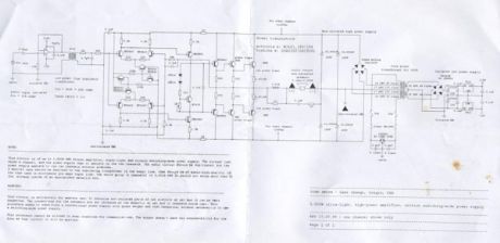
This circuit is of an 2x 2,500W RMS stereo amplifier, super-light and without switching-mode power supply. The circuit just shows a channel, and the power supply that it assists to the two channels. The audio circuit should be duplicated, but the power supply assists to the two channels without problems.
A special care should be destined to the insulating transformer of the audio line, that should be of audio-high-quality, of the type used in microphone pre amps input line. The whole group (2 channels) of 5,000W RMS it should not weigh more than 32 lbs, already inside of an appropriate metallic box. (View)
View full Circuit Diagram | Comments | Reading(1598)
150W MP3 car amplifier
Published:2012/10/12 22:29:00 Author:muriel | Keyword: 150W, MP3, car amplifier
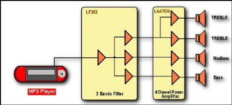
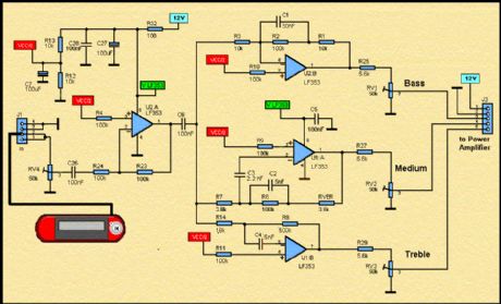
Here, it is a diagramm of an active loudspeaker. The LF353 of, National Semiconductor, is going to split audio signal into three bands. SANYO'S LA47536 is going to amplify these signals. In stereo mode, we shall have the action of eight high speakers who are going to create a very important sound pressure.
Three Band Active Tone Control:
LF353 Wide Bandwidth Dual JFET Input Operational Amplifier General Description These devices are low cost, high speed, dual JFET input operational amplifiers with an internally trimmed input offset voltage (BI-FET II technology). They require low supply current yet maintain a large gain band width product and fast slew rate. In addition, well matched high voltage JFET input devices provide very low input bias and offset currents. The LF353 is pin compatible with the standard LM1558 allowing designers to immediately upgrade e the overall performance of existing LM1558 and LM358 designs. These amplifiers may be used in applications such as high speed integrators, fast D/A converters, sample and hold circuits and many other circuits requiring low input offset voltage, low input bias current, high input impedance, high slew rate and wide bandwidth. The devices also exhibit low noise and offset voltage drift. (National Semiconductor) (View)
View full Circuit Diagram | Comments | Reading(1573)
10W Mini Audio Amplifier Circuit
Published:2012/10/12 22:26:00 Author:muriel | Keyword: 10W, Mini, Audio Amplifier Circuit
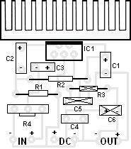
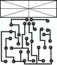
Componets ListR1 : 6 OhmR2 : 220 OhmR3 : nothingR4 : 10 KOhm pontesiometerC1 : 2200 uF / 25VC2 : 470 uF / 16VC3 : 470 nF / 63VC4 : 100 nFC5 : nothingC6 : nothingIC1 : TDA 2003 (View)
View full Circuit Diagram | Comments | Reading(1580)
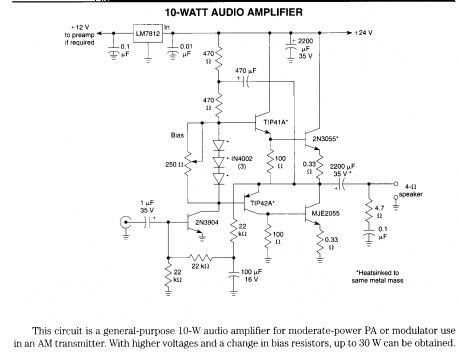
10-W audio amplifier
Published:2012/10/12 22:25:00 Author:muriel | Keyword: 10-W, audio amplifier
View full Circuit Diagram | Comments | Reading(3549)
10-14W Class A amplifier
Published:2012/10/12 22:24:00 Author:muriel | Keyword: 10-14W, Class A amplifier
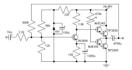
I have built this amplifier and it does sound good. It requires a preamp as it hasn't got much gain. It requires big heat sinks and a large transformer and a great power supply and careful wiring, but in the end it is extremely simple and it sounds very good. The zener diode rejects any ripple coming from the power supply, But you still only want a ripple of 10mV max. The ripple reaching the input is amplified, so the zener gets rid of that, but whatever ripple there is will still reach the power stage. (View)
View full Circuit Diagram | Comments | Reading(1297)
100W Audio Amplifier
Published:2012/10/12 22:22:00 Author:muriel | Keyword: 100W, Audio Amplifier


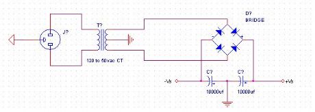
When I was around 17 years old, I acquired electronic habilities during my free time. Music also being one of my hobbies, I decided to use my electronic knowledge to build an audio amplifier. While my amplifier is not the most powerful that exists, it outputs a good quality of sound. It also has succesfully passed the party test . This means it has played as loud as possible without (intolerable) distortion for many hours hours, in a 3-4 ohms load.
Power-supply:I used a 110 volts to 50 volts ac transforer with a center tap. (this means +50 volts and -50volts). Next, I rectify the current with a diode bridge(big enough for 8A), and I filter with 2 big capacitors of 10000uf each.
(View)
View full Circuit Diagram | Comments | Reading(1055)
10 Watt Amplifier Schematic
Published:2012/10/12 22:18:00 Author:muriel | Keyword: 10 Watt, Amplifier
View full Circuit Diagram | Comments | Reading(1336)
1.5w 12v audio amplifier
Published:2012/10/12 22:17:00 Author:muriel | Keyword: 1.5w, 12v, audio amplifier

View full Circuit Diagram | Comments | Reading(3390)
One Watt 2.45 GHz Linear Amplifier
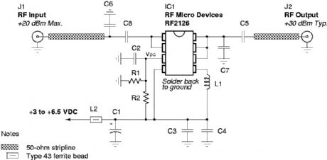
Published:2012/10/12 22:14:00 Author:muriel | Keyword: One Watt, 2.45 GHz , Linear Amplifier

View full Circuit Diagram | Comments | Reading(968)
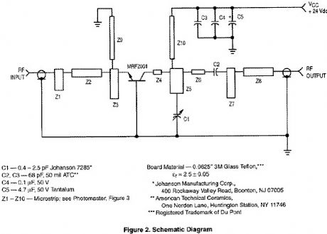
1 Watt 2.3 GHz RF Amplifier Using a MRF2001
Published:2012/10/12 22:13:00 Author:muriel | Keyword: 1 Watt, 2.3 GHz, RF Amplifier
View full Circuit Diagram | Comments | Reading(960)
| Pages:42/250 At 204142434445464748495051525354555657585960Under 20 |
Circuit Categories
power supply circuit
Amplifier Circuit
Basic Circuit
LED and Light Circuit
Sensor Circuit
Signal Processing
Electrical Equipment Circuit
Control Circuit
Remote Control Circuit
A/D-D/A Converter Circuit
Audio Circuit
Measuring and Test Circuit
Communication Circuit
Computer-Related Circuit
555 Circuit
Automotive Circuit
Repairing Circuit