
Amplifier Circuit
Index 59
An amplifier with gain controlled by frequency(LTC1043)
Published:2011/9/8 6:35:00 Author:Felicity | Keyword: amplifier, gain controlled by frequency
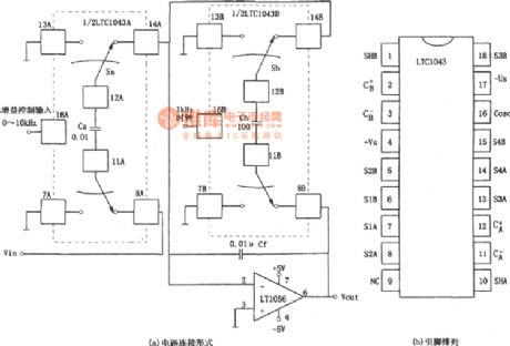
View full Circuit Diagram | Comments | Reading(805)
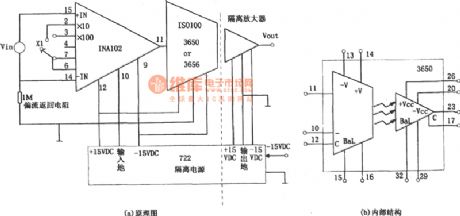
A isolation amplifier composed of ISO122 with programmable gain
Published:2011/9/8 6:30:00 Author:Felicity | Keyword: isolation amplifier, programmable gain

View full Circuit Diagram | Comments | Reading(1059)
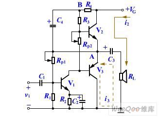
Deep-current negative feedback differential motion amplifier diagram
Published:2011/9/7 4:19:00 Author:Vicky | Keyword: deep-current, negative feedback, differential motion amplifier
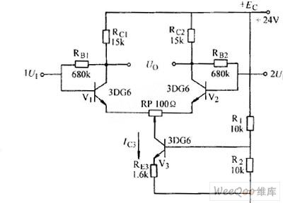
Deep-current negative feedback differential motion amplifier diagram
(View)
View full Circuit Diagram | Comments | Reading(964)
100KHz –100 MHz Noise Elimination Circuit Diagram
Published:2011/9/6 21:18:00 Author:Vicky | Keyword: noise elimination circuit
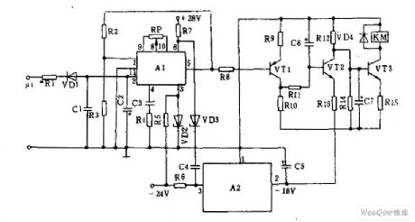
Noise elimination circuit can be designed in the 100kHz~l00MHz superhigh circuit. It is mainly composed by squelch amplifier AL, control circuit VTl~VT3, relay KNf, and regulated voltage supply A2. The working principle is shown in the above picture. When there is no signal received, the output noise voltage of superhigh frequency is lower than 100MV; the DC voltage of detection wave is very small after being filtered by diode VD1 and capacitances C1 and C2. The voltage enters the integrated amplifier A1via pin ② in the output end , and leaves via @. The voltage remains very small after amplified and cannot drive the triode VT1 to work. VT2 stops working and VT3 is under conducted. Relay KM then works.
(View)
View full Circuit Diagram | Comments | Reading(1287)
The edge detection circuit using NAND gate
Published:2011/8/8 0:17:00 Author:Sophia | Keyword: edge detection circuit, NAND gate
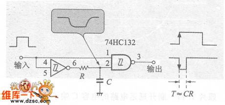
This circuit is the rising edge detection circuit using the NAND gate previously described, and circuit edge of the output pulse amplitude as T ≈ RC, IC threshold voltage CMOS, T ≈ 0.7RC.
In this circuit, when the input is L , the terminal voltage charge of capacitor C is voltage yDD and becomes high level H . When the input is H , before the C terminal voltage reaches y (T = RC), the output level is L . The figure is the input and output waveform of the edge detection circuit. 10pμs negative pulse will be got since the input begins to rise. (View)
View full Circuit Diagram | Comments | Reading(3449)
CMOS operational amplifier drive circuit
Published:2011/8/31 2:17:00 Author:John | Keyword: CMOS operational amplifier
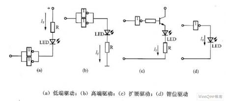
Figure shows the CMOS operational amplifier drive circuit. As the output current of CMOS operational amplifier is generally small, a few blocks of CMOS operational amplifiers should be set in parallel for driving the LED, as shown in Figure (a) and Figure (b). Sometimes, a CMOS operational amplifier transistor can be added to extend the drive current, as shown in Figure (c). In the circuit shown in Figure (d), once driven, CMOS operational amplifier’s output voltage can be incurred by LED clamp around the UF.
(View)
View full Circuit Diagram | Comments | Reading(845)
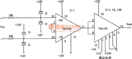
The gain programmable instrument amplifier composed of INA102
Published:2011/8/13 3:11:00 Author:qqtang | Keyword: gain, programmable, instrument amplifier
View full Circuit Diagram | Comments | Reading(909)
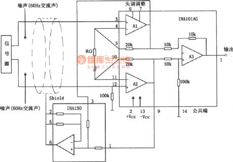
The instrument amplifier of removing AC sound (INA101)
Published:2011/8/13 3:09:00 Author:qqtang | Keyword: instrument amplifier, AC sound
View full Circuit Diagram | Comments | Reading(909)
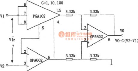
The gain programmable high speed instrument amplifier composed (PGA102 and OPA602)
Published:2011/8/13 3:14:00 Author:qqtang | Keyword: gain, programmable, high speed, instrument amplifier
View full Circuit Diagram | Comments | Reading(820)
The precise separating instrument amplifier (INA102)
Published:2011/8/13 3:16:00 Author:qqtang | Keyword: precise, instrument amplifier
View full Circuit Diagram | Comments | Reading(806)
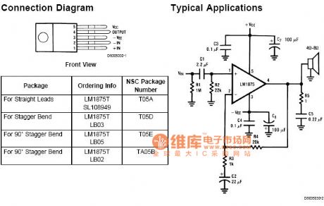
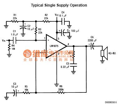
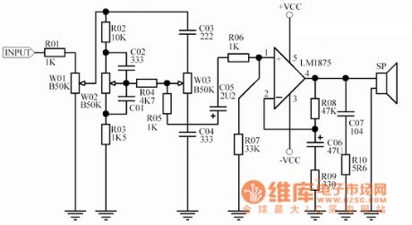
Lm1875T Hi-Fi 30w audio power amplifier circuit diagram 1
Published:2011/8/19 1:10:00 Author:Jessie | Keyword: Hi-Fi , 30w , audio power amplifier
View full Circuit Diagram | Comments | Reading(3311)
Lm1875T Hi-Fi 30w audio power amplifier circuit diagram 2
Published:2011/8/19 0:58:00 Author:Jessie | Keyword: Hi-Fi , 30w audio, power amplifier
View full Circuit Diagram | Comments | Reading(3858)
Lm1875T Hi-Fi 30w audio power amplifier circuit diagram 3
Published:2011/8/19 0:59:00 Author:Jessie | Keyword: Hi-Fi , 30w , audio power amplifier
View full Circuit Diagram | Comments | Reading(4554)
The OTL power amplifier circuit made of TDA2030A
Published:2011/8/23 22:11:00 Author:Borg | Keyword: power amplifier, OTL
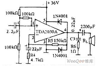
The OTL power amplifier is powered by a single supply and it is fixed with an output coupling capacitor. See as the figure, R5 (150 kΩ) and R4 (4.7 kΩ) decide the gain of the amplifier closed loop, the lower the resistance of R4 is, the higher the gain will be, but high gain can lead to the distortion of the signal. The 2 LEDs are connected between the power supply and the output terminal, which is used to prevent the inverting of the loudspeaker inductance load from affecting the sound quality, C3(0.22 uF) and R6(1 Ω) are used to compensate the phase of the inducting load (loudspeaker), so the self-motivation is gone, the circuit is powered by a 36V single power supply.
(View)
View full Circuit Diagram | Comments | Reading(3856)
The OTL power amplifier circuit composed of TDA2030A
Published:2011/8/23 22:11:00 Author:Borg | Keyword: power amplifier, OTL
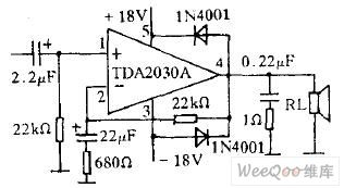
The OCL power amplifier type is to use dual power supply without any coupling capacitor, see as the figure, as there is no output coupling capacitor, the low frequency reaction is improved, so it is a hi-fi circuit. The dual power supply is fixed with a transformer whose primary coil middle point is connected with the ground and the voltages of the upper and lower are symmetric, after being rectified and filtered, a ±18V dual power supply is formed, whose output power is 20W.
(View)
View full Circuit Diagram | Comments | Reading(1259)
The BTL power amplifier circuit made of TDA2030A
Published:2011/8/23 22:12:00 Author:Borg | Keyword: BTL, power amplifier
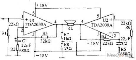
The main features of BTL are as follows: it consists of 2 power amplifiers of the same functions, and the input signals are inverting. In fact, both the inverting input and non-inverting input are used to make sure the input signals are inverting, at the same time, their amplitudes are the same, so the requirement of BTL circuit can be satisfied. The circuit is shown in the figure, after R7(1 kΩ) and R8(33 Ω) distribute the signal, the attenuating times are equal to the amplified times of U1, and the attenuated signal is added on the inverting terminal of U2 by R5.
(View)
View full Circuit Diagram | Comments | Reading(3778)
The single power supply amplifier circuit with a bootstrap circuit
Published:2011/8/23 22:12:00 Author:Borg | Keyword: single power supply, amplifier, bootstrap circuit
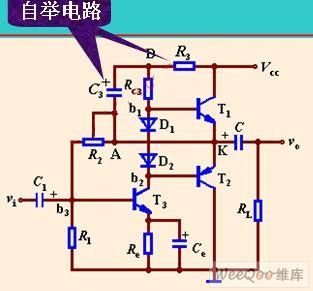
The single power supply amplifier circuit with a bootstrap circuit is shown in the figure.
(View)
View full Circuit Diagram | Comments | Reading(1793)
The voltage amplifier circuit of the electric charge amplifier
Published:2011/8/23 22:13:00 Author:Borg | Keyword: voltage amplifier, electric charge amplifier
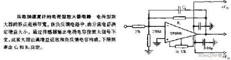
The voltage amplifier circuit of the electric charge amplifier The feature of the the electric charge amplifier is the wide frequency band. In the backward feedback circuit, as the distributing circuit determines the gain, the signal is stabilized by the cable capacitor output by the sensor. This amplifier consists of the high gain op-amp and backward feedback capacitor, and the lower limit frequency is decided by C1 and R1.
(View)
View full Circuit Diagram | Comments | Reading(1127)
The thermocouple isolated amplifier circuit
Published:2011/8/23 22:13:00 Author:Borg | Keyword: thermocouple, isolated amplifier
Working principles: Q1 is the pre-amplifier tube, which is using the NPN silicon tube, its temperature stability is good. To reduce the noise, the front stage is the key, or the noise will be noticeable after it is amplified at the following stages. The most importance is to avoid the noise being input from the base electrode. In this circuit, the base electrode power supply of Q1 is got after it is stabilized by D1 and D2, which improves the stability further. The resistance of the emitter resistor R4, which has little effect on the stable and still working point, it fulfills the function of AC backward feedback. (View)
View full Circuit Diagram | Comments | Reading(1219)
The voltage amplifier circuit of the piezoelectric accelerator
Published:2011/8/23 22:13:00 Author:Borg | Keyword: voltage amplifier, piezoelectric accelerator
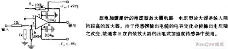
The voltage amplifier circuit of the piezoelectric accelerator
The voltage amplifier is an amplifier circuit with a high input impedance, as the capacitance change of the sensor output cable will make the output voltage change with it, so R is often used in the piezoelectric accelerating sensor with an amplifier inside it.
(View)
View full Circuit Diagram | Comments | Reading(854)
| Pages:59/250 At 204142434445464748495051525354555657585960Under 20 |
Circuit Categories
power supply circuit
Amplifier Circuit
Basic Circuit
LED and Light Circuit
Sensor Circuit
Signal Processing
Electrical Equipment Circuit
Control Circuit
Remote Control Circuit
A/D-D/A Converter Circuit
Audio Circuit
Measuring and Test Circuit
Communication Circuit
Computer-Related Circuit
555 Circuit
Automotive Circuit
Repairing Circuit