
Amplifier Circuit
Index 45
Tubes Tauro VAA 70 power amplifier circuit diagram
Published:2012/9/13 22:18:00 Author:Ecco | Keyword: Tubes Tauro , power amplifier
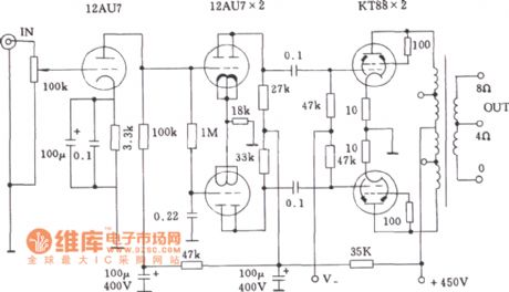
Tubes Tauro VAA 70 amp's primary of output transformer has two sets of taps which can be configured in two configurations: the first is the triode connection with high fidelity, stable performance, and its output power is 30W; the second is the ultra - linear connection with high working efficiency, the output power is 60W.
(View)
View full Circuit Diagram | Comments | Reading(1373)
1W Linear FM Booster
Published:2012/9/13 20:55:00 Author:Ecco | Keyword: 1W, Linear FM Booster
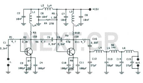
That RF Amplifier is for boosting small fm transmitters and bugs. It use two Philips 2N4427 and its power is about 1Watt. At the output you can drive any linear with BGY133 or BLY87 and so on. Its power supply has to give 500mA current at 12 Volts. More voltage can boost the distance but the transistors will be burned much earlier than usual.! In any case do not exceed the 15Volts.
Source: NEXT.GR (View)
View full Circuit Diagram | Comments | Reading(1583)
50W Hi-Fi amplifier with TDA7294
Published:2012/9/13 20:51:00 Author:Ecco | Keyword: 50W, Hi-Fi amplifier
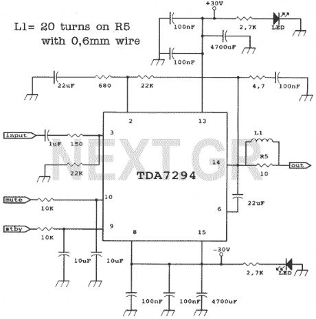
The TDA7294 is a Hi-Fi amplifier and can give 100W RMS but with 10% distortion. Supplying 30 Volts you can have 50 Watts RMS with 1% distortion. Frequency range start at 16Hz and can reach 100KHz. Make sure you are using good heatsink. The chip supports mute function as well.
Source: NEXT.GR (View)
View full Circuit Diagram | Comments | Reading(2733)
Amplifier input signal overdrive auto-protection
Published:2012/9/13 20:39:00 Author:Ecco | Keyword: Amplifier input, signal overdrive , auto-protection
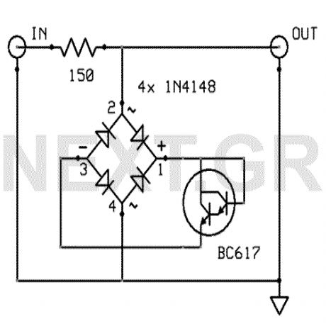
That circuit protects the overdriven signals going into an amplifier. Instead of a zener diode we use a transistor. That way we ensure that the above the ordinary input voltages ( 1 volt r.m.s.) can be acheaved without distortion. Also the use of a transistor limits the number of components used in this schematic.
Source: NEXT.GR (View)
View full Circuit Diagram | Comments | Reading(1479)
5 Watt UHF TV Linear amplifier
Published:2012/9/12 21:17:00 Author:Ecco | Keyword: 5 Watt , UHF , TV Linear amplifier
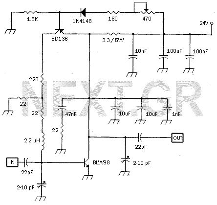
This small circuit is a Linear amplifier for driving small UHF TV transmitters. Its gain is 7dB and can amplify a signal between 450-800 MHz. You can drive the circuit with 1 to 1,5 Watts signal. Better use double layer PCB with the second layer connected to earth. Use a stabilized power supply 25 volts and at least 5Amps.
Source: NEXT.GR (View)
View full Circuit Diagram | Comments | Reading(1736)
4Watt UHF TV linear amplifier
Published:2012/9/12 21:17:00 Author:Ecco | Keyword: 4Watt , UHF TV , linear amplifier
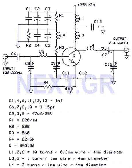
That Circuit is a UHF TV linear amplifier for small TV transmitters with output aroun 100-200mW. The transistor BGQ136 comes with SOT-122 case has gain of 13dB at 800MHz. So with input 100mW you get 2W output and for 200mW you get 4W.
Source: NEXT.GR (View)
View full Circuit Diagram | Comments | Reading(2207)
22 Watt power amplifier with TDA2040V
Published:2012/9/12 20:57:00 Author:Ecco | Keyword: 22 Watt , power amplifier

This circuit uses the TDA2040V which is a monolithic power amplifier IC intended for use as a high quality, class AB audio power amplifier. Typically it provides 22W output power into 4ohm with 0.5% distortion, from 32V supply. The device is designed to operate from a split power supply and no electrical isolation is needed between the mounting tab and its heatsink. It provides a high output current and has very low harmonic and crossover distortion.
Source: NEXT.GR (View)
View full Circuit Diagram | Comments | Reading(936)
2 Watt stereo amplifier with LM1877N-9
Published:2012/9/12 20:57:00 Author:Ecco | Keyword: 2 Watt, stereo amplifier
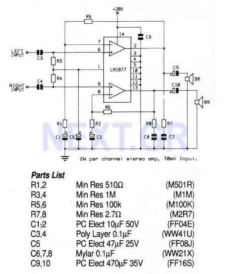
This circuit uses a stereo amplifier IC in a 14-pin DIL package that requires very few external components to make a complete 2 Watt per channel power amplifier. (View)
View full Circuit Diagram | Comments | Reading(2508)
40 Watt Audio power Amplifier LM3876
Published:2012/9/12 20:55:00 Author:Ecco | Keyword: 40 Watt, Audio power Amplifier

This Circuit is based on the LM3876. A 11-pin plastic package IC with high performance audio power amplifier, an output mute function which can be used to eliminate switch-on and switch-off thumps to the loudspeaker load. It is capable of delivering 40W continuously into 8ohm load, and is fully protected using established techniques. The output stage is protected against short circuit to ground or either supply rail. Protection against transients from inductive loads is also provided at the output stage via internal clamp diodes.
Source: NEXT.GR (View)
View full Circuit Diagram | Comments | Reading(2676)
40 Watt Hi-Fi amplifier (TDA1514AN-7)
Published:2012/9/12 20:54:00 Author:Ecco | Keyword: 40 Watt, Hi-Fi amplifier
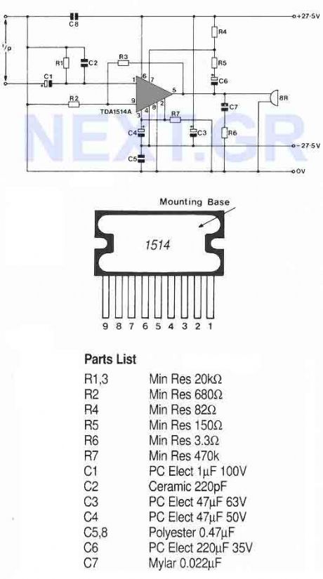
This very high quality audio amp is based on the TDA1514A, a 9-pin flat package IC. The heatsink must be insulated from ground. The amplifier will deliver 40 watt into an 8ohm load with a 27.5 volt power rail or 40 watt into 4ohm load with a 21 volt power rail. The IC is designed to meet the requirements of digital sound sources such compact disk players etc. The total harmonic distortion at 32watt is less than 0.0032%.
Source: NEXT.GR (View)
View full Circuit Diagram | Comments | Reading(1446)
TDA2050V HiFi amplifier
Published:2012/9/12 20:53:00 Author:Ecco | Keyword: HiFi amplifier
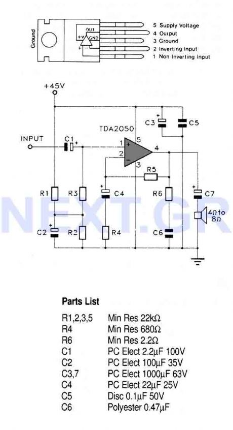
This circuit uses a high quality audio amplifier IC in a 5-pin TO220 package that does not require insulating washers between the metal tab and heatsink in single rail supply applications. The amp can provide 32 watt rms into 4ohm load and 25 watt rms into 8ohm. (View)
View full Circuit Diagram | Comments | Reading(1411)
TV signal amplifier 470Mhz-860Mhz
Published:2012/9/12 20:49:00 Author:Ecco | Keyword: TV , signal amplifier, 470Mhz-860Mhz

This amplifier can amplify to 10dB the RF signal from antenna working as class A and is based on transistor BFQ34 of Philips. The transistor comes in case SOT122A. You may find the BFQ34T in market but better do not use it as it has different characteristics. (View)
View full Circuit Diagram | Comments | Reading(1666)
HI-FI Audio Amplifier 60W
Published:2012/9/12 20:48:00 Author:Ecco | Keyword: HI-FI Audio Amplifier, 60W
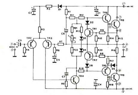
This amplifier has a high quality circuit that includes full sort circuit protection and very low T.H.D. at full range of frequency. It needs simmetrical power supply +-40V. The power transistors at the output are connected as DARLINGTON and both needs heatsinks. The power can reach 60 watts at 8 ohms or 80 Watts at 4 ohms. (View)
View full Circuit Diagram | Comments | Reading(3352)
PC audio amplifier 12Watt
Published:2012/9/12 20:45:00 Author:Ecco | Keyword: PC, audio amplifier, 12Watt
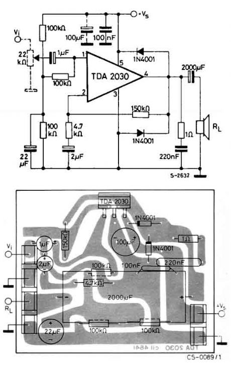
The circuit uses the TDA2030 which is a monolithic integrated circuit in Pentawatt? package, intended for use as a low frequency class AB amplifier. Typically it provides 14W output power (d = 0.5%) at 14V/4??; at ± 14V or 28V, the guaranteed output power is 12W on a 4?? load and 8W on a 8?? (DIN45500). The TDA2030 provides high output current and has very low harmonic and cross-over distortion. (View)
View full Circuit Diagram | Comments | Reading(2129)
10Watt HI-FI Amplifier (TDA2002)
Published:2012/9/12 20:44:00 Author:Ecco | Keyword: 10Watt, HI-FI Amplifier

A very small but good quality amplifier circuit that is also fairly cheap. It is based on TDA2002 which offers very low distrortion. Power should be 12-15 volt 1,2A. The amplifier frequency responce ranges from 40Hz to 15Khz. A good heatsink is required. At the input you can connect your mp3 player or your pc audio out etc. (View)
View full Circuit Diagram | Comments | Reading(6463)
AM-FM-TV RF AMPLIFIER
Published:2012/9/12 20:44:00 Author:Ecco | Keyword: AM-FM-TV, RF AMPLIFIER
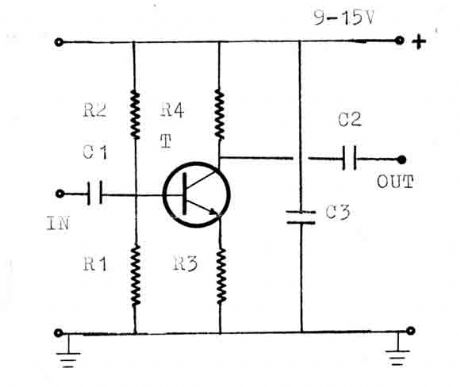
The circuit is a universal amplifier that can amplify any rf signal. You can use the BF194 or the BF198. Make sure you use coaxial cable. (View)
View full Circuit Diagram | Comments | Reading(4254)
Offset controlled stereo amplifier circuit
Published:2012/9/11 21:31:00 Author:Ecco | Keyword: Offset , controlled , stereo amplifier
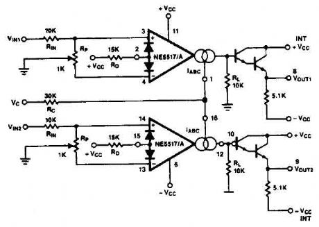
This stereo amplifier use the NE5517/A and has an excellent tracking of 0.3 dB typical easy. With the potentiometer, Rp, the offset can be adjusted. For AC-coupled amplifiers, the knob can be replaced by two resistors 5.1 k ohm. (View)
View full Circuit Diagram | Comments | Reading(1956)
CMOS inverters linear amplifier circuit
Published:2012/9/11 21:26:00 Author:Ecco | Keyword: CMOS inverter, linear amplifier
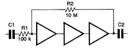
CMOS inverters can be used as linear amplifiers where negative feedback is applied. Best linearity is achieved with feedback applied around three inverters which gives almost perfect linearity up to a dynamic output of 5 V peak to peak with a 10 V supply rail The gain is set by the ratio of Rl and R2 and the values are typical for a gain of 100. The high frequency response with the values given is almost flat to 20 kHz. The frequency response is determined by Cl and C2. (View)
View full Circuit Diagram | Comments | Reading(2261)
HiFi expandor with De-emphasis
Published:2012/9/11 21:25:00 Author:Ecco | Keyword: HiFi expandor , De-emphasis
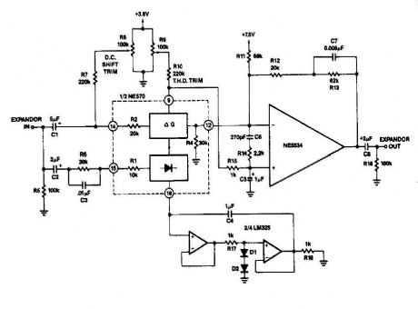
it can reduce its gain. The time it takes for the compressor to recover from overload is determined by the rectifier The expander eg capacitor to complete the compressor is shown in FIG. 2-13B. Here is an external op amp is used for the high rate of ascent. The compressor and expander have unity gain at 0 dB. Trim networks are shown for distortion (THD) and DC offset. (View)
View full Circuit Diagram | Comments | Reading(3530)
Attenuator circuit
Published:2012/9/11 20:27:00 Author:Ecco | Keyword: Attenuator
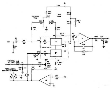
A op amp and transistors Q1 and Q2 exponential converter to generate an exponential gain control current, which is introduced into the rectifier. A reference current of 150 pA, (15 V and RZO = lOO-k), is attenuated by a factor of two (6 dB) for each increase of tension in the control voltage. Capacitor C6 slows secure changes to a period of 20 IDS constant (C6 x IR) such that a sudden change in the control voltage will produce a gain change smooth sound. RI8 ensures that for control voltages of the circuit will go to great attentuation full. (View)
View full Circuit Diagram | Comments | Reading(1323)
| Pages:45/250 At 204142434445464748495051525354555657585960Under 20 |
Circuit Categories
power supply circuit
Amplifier Circuit
Basic Circuit
LED and Light Circuit
Sensor Circuit
Signal Processing
Electrical Equipment Circuit
Control Circuit
Remote Control Circuit
A/D-D/A Converter Circuit
Audio Circuit
Measuring and Test Circuit
Communication Circuit
Computer-Related Circuit
555 Circuit
Automotive Circuit
Repairing Circuit