
Amplifier Circuit
Index 61
The intelligent digital voltmeter composed of HI7159A and 8031 single chip machine
Published:2011/8/23 22:39:00 Author:qqtang | Keyword: digital voltmeter, single chip machine
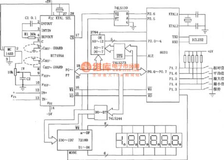
The intelligent digital voltmeter composed of HI7159A and 8031 single chip machine is shown in the figure. The circuit is equipped with gradual accumulation integration, digital zero set, low noise BIMOS and other technologies. The maximum counting value is 199999 under the working mode of 5 1/2, its precision is ±0.005%. (View)
View full Circuit Diagram | Comments | Reading(1516)
The single machine reset circuit
Published:2011/8/23 22:39:00 Author:qqtang | Keyword: single machine, reset circuit
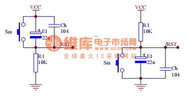
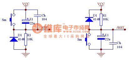
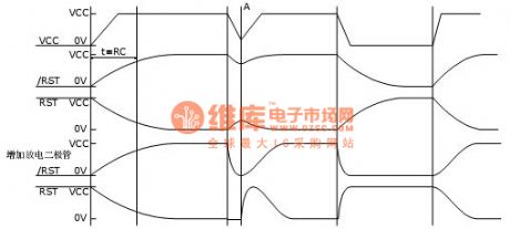
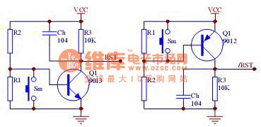
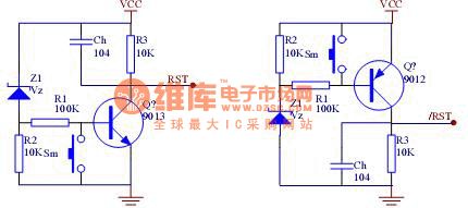
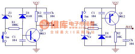
Figure 2 by increasing the RC reset circuit of the discharging circuit and using the comparator circuit, it can not only solve the problem of the system instability caused by the power supply burr, but also the power supply will fall down or reset reliably. Figure 4 is an practical example, when VCC x (R1/(R1+R2) ) =0.7V, Q1 is blocked and the system is reset. The amplifying function of Q1 can also improve the loading character of the circuit, but its obvious defect is that hop sill voltage Vt is affected by VCC, but the use of diode can avoid this problem.
Figure 3 the input-output feature of RC reset circuit
(View)
View full Circuit Diagram | Comments | Reading(1201)
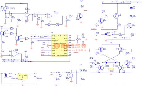
Electromotor servo amplifier composed of the power MOSFET
Published:2011/8/26 0:50:00 Author:TaoXi | Keyword: Electromotor, servo amplifier, power MOSFET
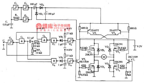
The electromotor servo amplifier composed of the power MOSFET is as shown in the figure. The MOSFET grid electrode driving boost circuit is composed of the G1-G3, the oscillation frequency is 20KHz, it is decided by the R1 and C1. The benchmark pulse generating circuit is composed of the G4 and G5, the RP1 can be used to adjust the midpoint voltage, the Ui is the output control siganl; the pulse width comparison circuit is composed of G7 and G8; the pulse stretcher circuit is composed of G9 and G10; the MOSFET grid electrode excitation circuit is composed of the VTl, VT2, VT7 and VT8, the electromotor driving circuit is composed of VT3-VT6.
(View)
View full Circuit Diagram | Comments | Reading(2303)
The power failure protection circuit of the single chip system
Published:2011/8/23 22:39:00 Author:qqtang | Keyword: power failure, protection circuit, single chip system
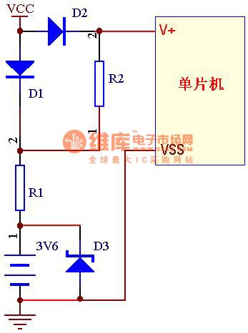
When the main power is normal, the signal chip machine is powered by VCC5V, at the moment, the VCC5V power supply is charging the battery through D1 and R1, by which the fullness of the battery volume can be ensured. If the right resistor R1 is chosen, then the charging current and charge time will be proper. For example, when charging 3V6 * 60mAH battery, the charge time is about 8h, then we choose the charge current as 8mA, R1=(6V-0.6)/8(0.6 is the conducting step-down of the serial diode). (View)
View full Circuit Diagram | Comments | Reading(811)
The automatic flush device circuit
Published:2011/8/13 2:05:00 Author:qqtang | Keyword: automatic flush device
View full Circuit Diagram | Comments | Reading(1298)
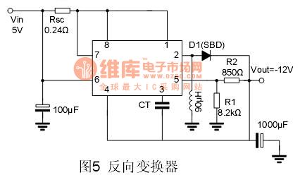
The backward converter of MC34063 application circuit
Published:2011/8/13 1:51:00 Author:qqtang | Keyword: backward converter, application circuit
View full Circuit Diagram | Comments | Reading(3076)
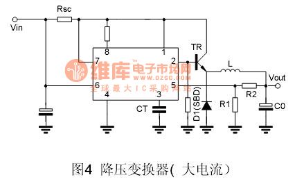
The step-down converter (large current) of MC34063 application circuit
Published:2011/8/13 1:57:00 Author:qqtang | Keyword: step-down converter, large current, application circuit
View full Circuit Diagram | Comments | Reading(5475)
The booster converter (large current) of MC34063 application circuit
Published:2011/8/13 1:59:00 Author:qqtang | Keyword: booster converter, large current, application circuit
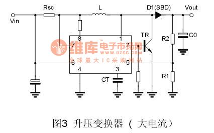
View full Circuit Diagram | Comments | Reading(3193)
The step-down converter of MC34063 application circuit
Published:2011/8/13 2:01:00 Author:qqtang | Keyword: step-down converter, application circuit
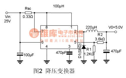
View full Circuit Diagram | Comments | Reading(3397)
The booster converter of MC34063 application circuit
Published:2011/8/13 2:02:00 Author:qqtang | Keyword: booster converter, application circuit
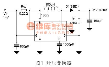
View full Circuit Diagram | Comments | Reading(6482)
The DC current measurement circuit
Published:2011/8/13 1:03:00 Author:qqtang | Keyword: DC current, measurement
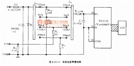
Figure 2-40-10 The DC current measurement circuit (View)
View full Circuit Diagram | Comments | Reading(1950)
The DC voltage test ciruit
Published:2011/8/13 1:05:00 Author:qqtang | Keyword: DC voltage, test ciruit
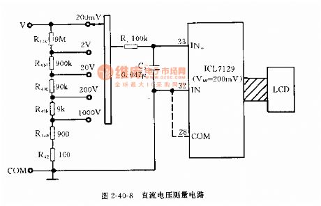
Figure 2-40-8 The DC voltage test ciruit (View)
View full Circuit Diagram | Comments | Reading(966)
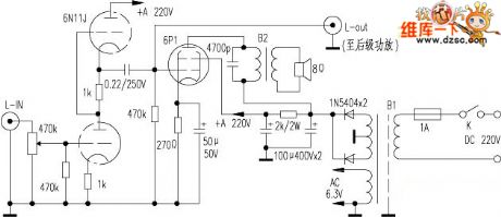
Dual valve power amp schematic
Published:2011/8/25 1:09:00 Author:Ecco | Keyword: Dual valve , power amp
View full Circuit Diagram | Comments | Reading(1022)
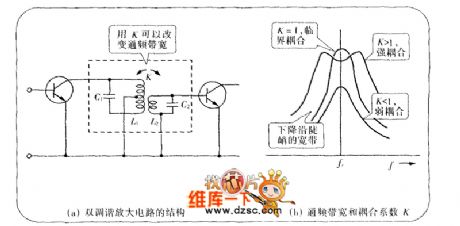
Double-tuned amplifier circuit diagram
Published:2011/8/25 1:48:00 Author:Ecco | Keyword: Double-tuned amplifier
View full Circuit Diagram | Comments | Reading(2691)
High Accuracy Constant Current Circuit
Published:2011/8/23 23:40:00 Author:Robert | Keyword: High, Accuracy, Constant, Current
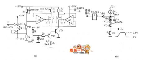
The picture shows the high accuracy constant current circuit and its practical application example. In the circuit shown in picture (a), it adds the grounding loop circuit between the constant current circuit and the load. Thus the current would return to be stable rapidly when the load has changed. The A1 and VT1 make up the voltage/current conversion circuit which could convert the ground voltage signal to the +15V voltage signal needed by the constant current circuit. The A2, VT2, VT3 etc. make up the standard constant current circuit. By setting R1=R2 it could provides the equal current I1=I2. VT5's base electrode is provided the +5V stable voltage by the zener diode VS1. So the VT5's emitter electrode voltage would keep +5.7V which would not be affected by the load changing. (View)
View full Circuit Diagram | Comments | Reading(1095)
The FM circuit composed of the NE555
Published:2011/8/23 22:28:00 Author: | Keyword: FM circuit
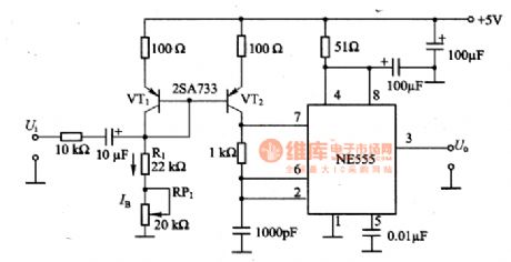
The FM circuit composed of the NE555 is as shown in the figure. By changing the charging current of the NE555 self-excited multivibrator, we can do the frequency modulation. This circuit is the current mueller circuit that is composed of VT1 and VT2, and it can produce the charging current in the charging circuit, the current is decided by R1 and RP1. The low frequency modulation signal and the offset current IB are overlied to make the oscillation frequency change. The current mueller circuit need to use the geminate transistor.
(View)
View full Circuit Diagram | Comments | Reading(2189)
AD827AQ, AD827JN double operation amplifier integrated circuit
Published:2011/8/23 22:27:00 Author: | Keyword: double operation, amplifier, integrated circuit
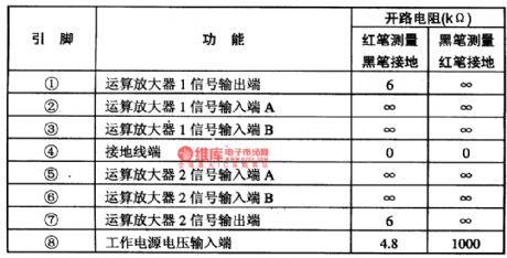
The AD827AQ and AD827JN are designed as one kind of double operation amplifier integrated circuit that is produced by the MD company, and it can be used in the sound equipment, the electrical equipment and the industrial automatic control electronic circuit.
The AD827AQ and AD827JN are in the dual-row DIP package, the package has two kinds: the ceramic package and the plastic package, if the suffix is AQ, it is the ceramic package, if the suffix is JN, it is the plastic package. They have the same internal structure, they are composed of two high precision operation amplifier circuits. The pin functions and data are as shown in table 1.
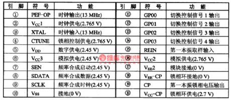
The AD6524 frequency synthesizer integrated circuit
The AD6524 frequency synthesizer integrated circuit can be used in all kinds of cellphones such as the TCL2188.etc.
(View)
View full Circuit Diagram | Comments | Reading(1018)
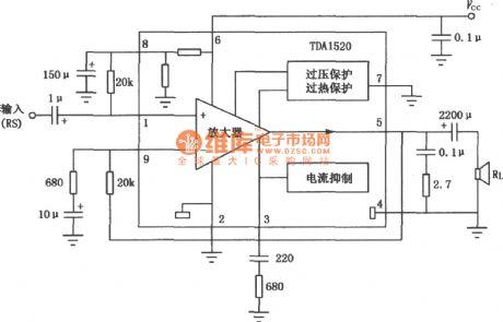
TDA1520 20W audio power amplifier circuit diagram
Published:2011/8/22 22:14:00 Author:Rebekka | Keyword: 20W, audio power amplifier
View full Circuit Diagram | Comments | Reading(3731)
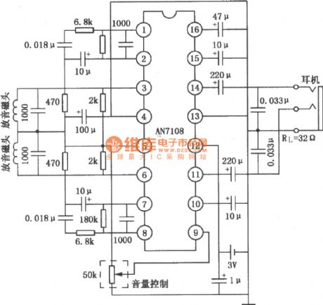
AN7108 Single stereo cassette player circuit diagram
Published:2011/8/22 22:23:00 Author:Rebekka | Keyword: Single, stereo cassette player
View full Circuit Diagram | Comments | Reading(2508)
ECC822 Tube OTL headphone amplifier circuit diagram
Published:2011/8/22 22:23:00 Author:Rebekka | Keyword: Tube OTL , headphone amplifier
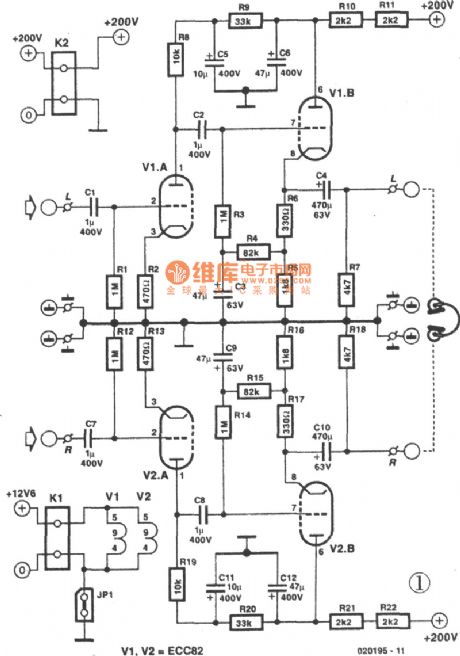
The tubehas the advantages ofgood index and long life. Preamplifier is used for driving headphones by generating sufficient signals. Then it outputs pre-amplifier stage directly through C1、R1. But R1、C1 must provide negative gate bias. Gain is essentially determined by the R8. The maximum input voltage is determined by the R2. R9: The static anode current is chosen in maximum possible part of characteristic curve. The input signals is inversed and enlarged on anode through C2 coupling to second level gate. The second stage cathode resistor is divided into two parts, R5 and R6. R5 and R6 form a load resistor in series.
(View)
View full Circuit Diagram | Comments | Reading(5856)
| Pages:61/250 At 206162636465666768697071727374757677787980Under 20 |
Circuit Categories
power supply circuit
Amplifier Circuit
Basic Circuit
LED and Light Circuit
Sensor Circuit
Signal Processing
Electrical Equipment Circuit
Control Circuit
Remote Control Circuit
A/D-D/A Converter Circuit
Audio Circuit
Measuring and Test Circuit
Communication Circuit
Computer-Related Circuit
555 Circuit
Automotive Circuit
Repairing Circuit