
Amplifier Circuit
Index 73
LOW_COST_USING_OPAMP
Published:2009/7/14 3:03:00 Author:May
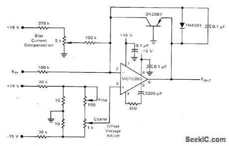
Motorola MC1539G opamp is connected with PNP transistor as logarithmic element. Circuit requires external compensation, has about 200-nA bias current, and accommodates wide range of input voltages when appropriate networks are used to compensate for errors. To adiust bias current initially, replaee transistor with 500K resistor and ad just 5K pot for gain of 5 over input signal range.-K. Huehne, Transistor Logarithmic Conversion Using an Integrated Operational Amplifier, Motorola, Phoenix, AZ, 1971, AN-261A, p 4. (View)
View full Circuit Diagram | Comments | Reading(884)
UNITY_GAIN_DIFFERENTIAL_D_C_AMPLIFIER
Published:2009/7/15 5:26:00 Author:Jessie
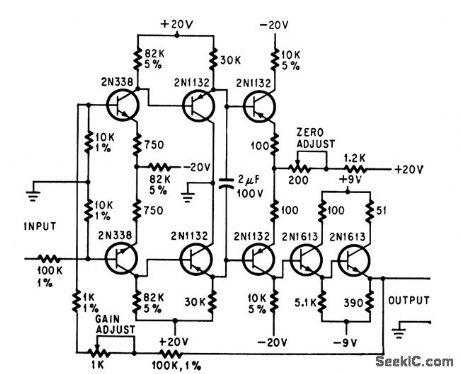
Negative feedback with differential input and single-ended output give gain stability of 1.0000 for output of 1.2V across 100-ohm load, for use in battery-powered transistor leakage-current tester.-A. T. Ashby, T. R. Shaifer, and H. R. Hegner, Testing Transistors In.-Circuit, Electronics, 37:17, p 53-56. (View)
View full Circuit Diagram | Comments | Reading(1086)
NO_CHOPPER_DIFFERENTIAL_AMPLIFIER
Published:2009/7/15 5:21:00 Author:Jessie
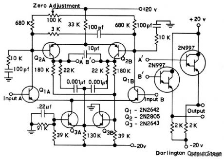
Stable voltage gain is 1,000.Current source Q2 provides bias for input stage. Amplification is linear within 10 microvolts over 100℃ range.-D. F. Hilbiber, Stable Differential Amplifier Designed Without Choppers, Electronics, 38:2, p 73-15. (View)
View full Circuit Diagram | Comments | Reading(1093)
DIRECT_COUPLED_DIFFERENTIAL_AMPLIFIER
Published:2009/7/15 5:17:00 Author:Jessie
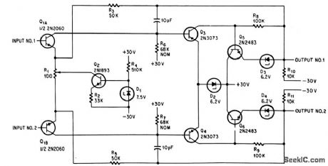
Designed for general use as complete amplifier with Darlington output stage, or as first two stages of low-drift high-gain amplifier without amplifier stage. Provides both low and high common. mode rejection for either differential or single-ended outputs. High common-mode rejection is achieved by use of common-mode feedback loop. Low drift is achieved by using dual transistor Q3 as first stage of common-mode feedback loop.-Texas Instruments Inc., Solid-State Communications, McGraw-Hill, N.Y. 1966, p 161. (View)
View full Circuit Diagram | Comments | Reading(976)
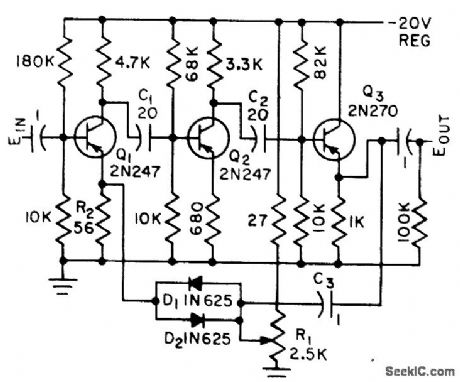
PREVENTS_AMPLIFIER_OVERLOAD
Published:2009/7/15 23:13:00 Author:Jessie
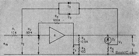
Zener 6.8-v diode shunts output while feedback diodes limit input. With input below 40 mv, output is below -5 v and diodes D1, D2, and D3 are biased off. When output exceeds -6.8 v, diodes act to damp output at -6.8 v und maintain linear voltage relationships within the amplifier, preventing its saturation and allowing recovery from overloads.-J. V. Dirocco and J. W, Peghiny, Low-Level Encoding Approach: Latest Details of Titan II Telemetery, Electronics, 35:47, p 36-39 (View)
View full Circuit Diagram | Comments | Reading(815)
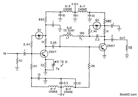
432_MHz_LOW_NOISE_PREAMP
Published:2009/7/15 23:04:00 Author:Jessie
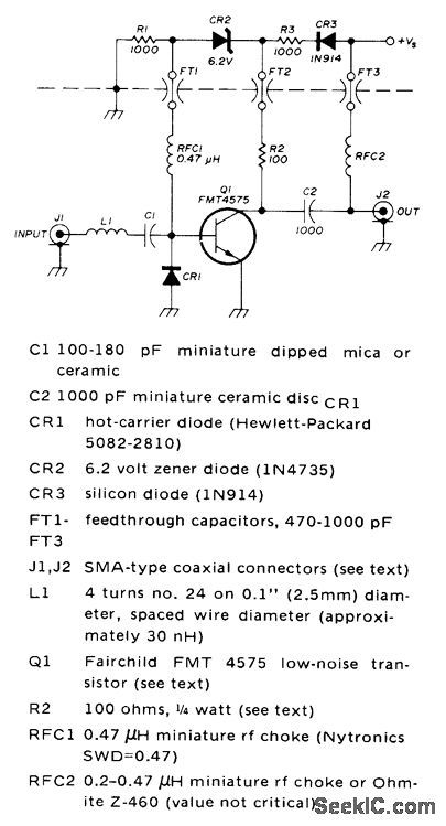
Uses Fairchild FMT4575 transistor having 1.25-dB noise figure, equaling performance of best paramps at 432 MHz. Input matching circuit is low-loss low-Q L matching section L1-CR1. Value of blocking capacitor C1 is not critical, but should be low-loss high-Q type, Hot-carrier diode CR1 in matching section adds about 0.75 pF to circuit, and serves also as low-loss limiter that protects transistor from excessive RF. Zener-diode biasing permits direct grounding of emitter, is insensitive to transistor current gain, provides some DC protection to transistor, and requires no adjustments.-J. H. Reisert, Jr., Ultra Low-Noise UHF Preamplifier, Ham Radio, March 1975, p 8-19. (View)
View full Circuit Diagram | Comments | Reading(1411)
LOGARITHMIC_PULSE_AMPIJFIER
Published:2009/7/15 22:56:00 Author:Jessie

Selected series with D1 for straightening curvet give rent, from0.1 to100 ma.-D. Ophir ond U. zener diodes with breakdown voltages in dose approximation to logarithmic ampli- Galil, Zener Diode creates Logarithmic Pulse range of 4 to 6 v, with 1.6 ohm.resistor in fication of pulses over three decades of cur Amplifier, Electronics, 34:28, p 68-70. (View)
View full Circuit Diagram | Comments | Reading(874)
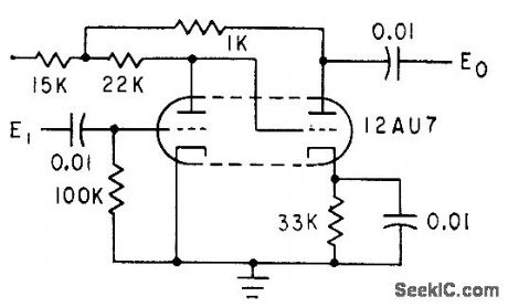
THREE_STAGE_NEGATIVE_PULSEAMPLIFIER
Published:2009/7/15 22:53:00 Author:Jessie
Handles closely spaced negative pulses in radar beacon and similctr applications, with-amplifier stctge is inverse-feedback pair of triodes with out distortion and recovery problems.Each amplifier stage is inverse-feednback pair of triodes with 360 ° total phase shift.-R. E. Koncen, Wide-Range Multiple-Pulse Amplifier, Electronics, 33:38, p 78-81. (View)
View full Circuit Diagram | Comments | Reading(739)
THYRATRON_DRIVER
Published:2009/7/15 22:49:00 Author:Jessie
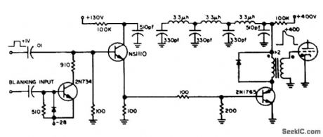
Input of 1 v makes solid-state circuit drive thyratron grid to 400 v within 60 nsec. Thyratron itself is fully on, and handling 100 amp al 6,000 v, in less than 100 nsec after input pulse. W. D. lsreal and W. B. McCartney, Nanosecond Thyratron Driver, EEE, 11:12, p 66. (View)
View full Circuit Diagram | Comments | Reading(1918)
FOUR_STAGE_NEGATIVE_PULSE_AMPLIFIER
Published:2009/7/15 22:48:00 Author:Jessie
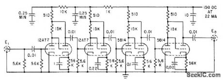
Gives gain of 87 db with over-all bandwidth of 0.9 Mc, using direct-coupled inverse-feed back pairs, for amplifying closely spaced pulse code groups coming from crystal detector of radar video receiver.-R. E. Koncen, Wide-Range Multiple-Pulse Amplifier, Electronics, 33:38, p 78-81. (View)
View full Circuit Diagram | Comments | Reading(729)
VIDEO_AMPLIFIER_WITH_TWONSEC_RISE_TIME
Published:2009/7/15 22:47:00 Author:Jessie
Uses feedback techniques with 1,000-Mc silicon lrcmsislors to give wide bandwidth and fast pulse response.-P. J. Beneteau and J. A Madntosh, Getting Fasl Pulse Response with Video Amplifers, Electronics, 34:41, p 62-63.
(View)
View full Circuit Diagram | Comments | Reading(905)
ANALOG_DIFFERENTIAL_AMPLIFIER
Published:2009/7/14 2:36:00 Author:May
Input impedance is above 300,000 ohms and output impedance 1 ohm, in d-c amplifier for analog input channel.Q3 and Q4 provide gain and phase inversion for feedback through complementary emitter-follower Q5-Q6 to differential amplifier Q1-Q2.-N. Aron and C.Granger, Analog-To-Digital Converter Uses Transfluxors, Electronics,35:20, p 62-66. (View)
View full Circuit Diagram | Comments | Reading(802)
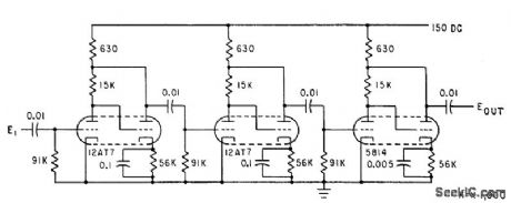
CRYSTAL_VIDEO_RECEIVER_AMPLIFIER
Published:2009/7/15 23:19:00 Author:Jessie
Modified direct-coupled inverse-feedback pair of triodes handles negative pulse groups only if not too closely spaced. May be used in command guidance, radar beacon, and pulse communication applications.-R. E. Koncen, Wide-Range Multiple-Pulse Amplifier, Electronics, 33:38, p 78-81. (View)
View full Circuit Diagram | Comments | Reading(789)
NONINVERTING_AMPLIFIER
Published:2009/7/15 23:17:00 Author:Jessie
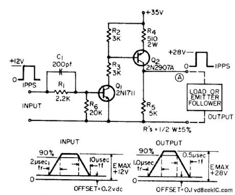
Increases amplitude of 1-pps pulses and decreases rise and fall times. For adjustable output amplitude, R5 can be potentiometer.-R. L. Sazpansky, Non-Inverting Pulse Amplifier Uses One Power Supply, EEE, 14:1, p 63. (View)
View full Circuit Diagram | Comments | Reading(0)
FAST_ACTING_NONLINEAR_FEEDBACK
Published:2009/7/15 23:15:00 Author:Jessie
Keeps output variation within 8 db for input level variation of 38 db. Amplifies 100-kc square waves and limits output amplitude without introducing phase distortion, Amplilcation is determined by input level. For signals below 5 my peak, 38 db of gain is provided, auto. matically diminishing for higher-level input signals. With 400.mY peak input, gain is slightly over unity.-L. H. Dulberger, Pulse Amplifer with Nonlinear Feedback, Electronics, 31:45, p 86-87. (View)
View full Circuit Diagram | Comments | Reading(760)
FAST_RISE_TIME
Published:2009/7/15 23:14:00 Author:Jessie
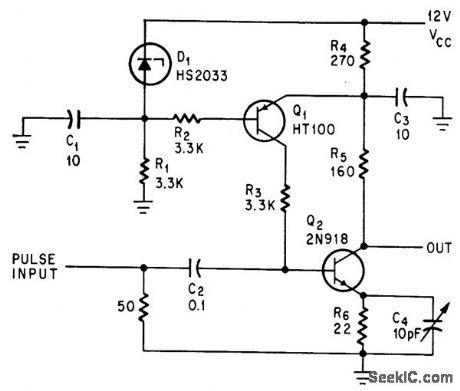
Achieved by precise bias control of Q2 without introducing pclrclsifics in input signal Iine. Gives high gain-band-width product as pulse amplifier.-D. D. McLeod, Bias Control and Low Parasitics Shorten Amplifier Rise Time, Elecnonics, 39:2, p 73-74. (View)
View full Circuit Diagram | Comments | Reading(1025)
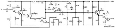
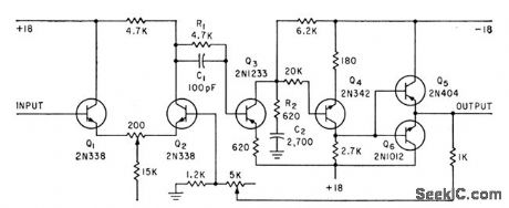
PULSE_POWER_AMPLIFIER
Published:2009/7/15 23:20:00 Author:Jessie
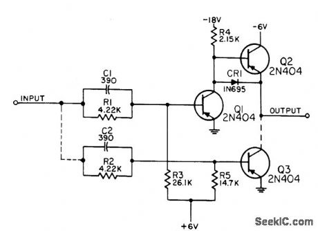
Operates as inverting power amplifier for either pulses or levels. Input levels are -6.2 v at 3.1 ma for logical 1 and -0.15 v for logical 0. Pulse polarity may be positive or negative 6 v. Third transistor is used for handling up to 40 flip-flop or gate loads. Two transistors will handle up to 12 such loads.-NBC, Hand-book Preferred Circuits Navy Aeronautical Electronic Equipment, Vol. II, Semiconductor Device Circuits, PSC 12 (originally PC 215), p 12-2. (View)
View full Circuit Diagram | Comments | Reading(1490)
LINEAR_PULSE_AMPLIFIER
Published:2009/7/15 22:44:00 Author:Jessie
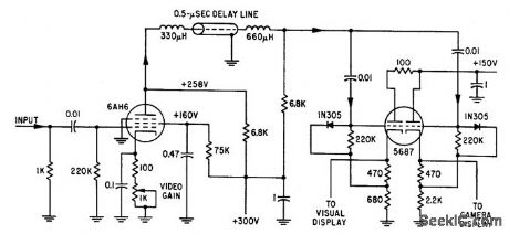
Simple linear amplifier drives two cathode followers through delay line. One output goes to one crt grid for intensity modulation. Other output goes to horizontal plates of another crt bar presentation.-M.T. Nador, Microsecond Sampler Handles 126 Channels, Electronics, 32:4, p 36-39. (View)
View full Circuit Diagram | Comments | Reading(1001)
NEGATIVERESISTANCE_DIODE
Published:2009/7/15 22:43:00 Author:Jessie
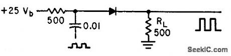
Input pulses as low as 0.01 ma are sufficient to hold negcttive-resistcmce diode in high-current region. When pulse is shut off, diode current decays to low.current state. Amplifier tends to square up input pulses.-A. P, Schmid, Jr., Negative4tesistcmce Diode Handles High Power, Electronics, 34:34, p 44-46. (View)
View full Circuit Diagram | Comments | Reading(774)
CURRENT_DRIVER
Published:2009/7/15 23:24:00 Author:Jessie
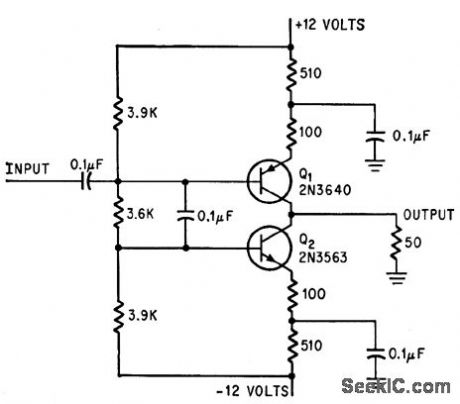
Provides fast rise time and equal-amplitude positive and negative output pulses (equal-polarity drive) for 50-ohm loud. -E. J. Kennedy, Fast-Pulse Amplifer Drives 50-Ohm Load, Electronics, 39:2, p 76. (View)
View full Circuit Diagram | Comments | Reading(1091)
| Pages:73/250 At 206162636465666768697071727374757677787980Under 20 |
Circuit Categories
power supply circuit
Amplifier Circuit
Basic Circuit
LED and Light Circuit
Sensor Circuit
Signal Processing
Electrical Equipment Circuit
Control Circuit
Remote Control Circuit
A/D-D/A Converter Circuit
Audio Circuit
Measuring and Test Circuit
Communication Circuit
Computer-Related Circuit
555 Circuit
Automotive Circuit
Repairing Circuit