
Amplifier Circuit
Index 63
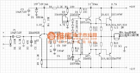
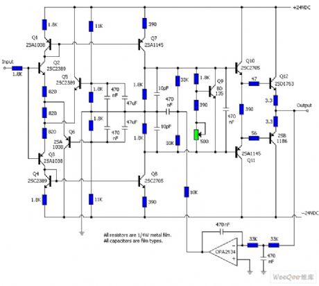
30W A-class OCL post amplifier circuit diagram
Published:2011/8/11 2:13:00 Author:Rebekka | Keyword: 30W A-class, OCL post amplifier
View full Circuit Diagram | Comments | Reading(1880)
Photoelectric isolated amplifier circuit composed of the ISO100
Published:2011/8/15 2:25:00 Author:Rebekka | Keyword: Photoelectric isolated amplifier
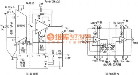
The figure shows the photoelectric isolated amplifier circuit. The photoelectric isolated amplifier can be used in the automatic control system, the data acquisition system, computer I/O interface and communications equipment. The photoelectric isolated amplifier is also called the photoelectric couplers, this device is a composite shell element that the light emitting components and the light components and packaging in the same relative set. The input and output contacts by light and ithas insulation to electric. It is the the solid component with completely an unique property and function. (View)
View full Circuit Diagram | Comments | Reading(675)
Bias compensation broadband amplification circuit diagram
Published:2011/8/11 2:11:00 Author:Rebekka | Keyword: Bias compensation, broadband amplification
The voltage amplifier multiples of the circuit parameters is: Av =-10, the voltage conversion speed is larger than 70 v/u s, half power bandwidth can be up to 400 kHz above, its gain products of bandwidth is about 30 MHz. The working temperature of the LH0003with10-pin metal circular encapsulates is 0 ~85 ℃. The storage temperature is 65 ~ 150 ℃. When it uses the LH0003 chip, its working temperature is 125 ℃ and 55, the storage temperature is 65 ~ 150 ℃. Figure (b) shows the LH0003 / LH0003C integrated chips tube feet arrangment diagram. (View)
View full Circuit Diagram | Comments | Reading(914)
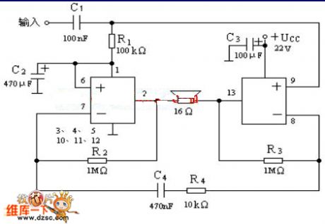
Mellow sound pure class A power amplifier circuit diagram
Published:2011/8/9 2:23:00 Author:Rebekka | Keyword: Mellow sound, pure class PA, power amplifier

View full Circuit Diagram | Comments | Reading(5263)
LM4911 Different power conduction time recommended circuit diagram
Published:2011/8/16 22:09:00 Author:Rebekka | Keyword: MOSFET, Different power , conduction time
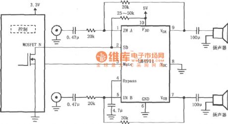
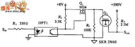
LM4911 Different power conduction time recommended circuit diagram is shown as below. The circuit uses a controller. The MOSEFT tube of the controller controls the LM4911 shutdown control (SD) end to achieve on-time regulation of the amplifier.
(View)
View full Circuit Diagram | Comments | Reading(740)
LM4915 Single-channel pseudo differential headphone amplifier circuit diagram
Published:2011/8/16 22:08:00 Author:Rebekka | Keyword: Single-channel pseudo differential, headphone amplifier
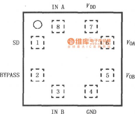
LM4915 is a pseudo-differential audio power amplifier. It is mainly used for demanding mono headset such as mobile phones and other portable audio devices. LM4915 uses 3V power supply. The average power is output 90mW and it drives 32Ω BTL load. LM4915 has a Low-power shutdown mode. Just drive control logic active low-side. LM4915 has an internal thermal shutdown protection agency. It contains a modified Cameroon - flapping sound elimination circuit. The internal fixed gain is set to 6dB. The pinout is shown as below.
(View)
View full Circuit Diagram | Comments | Reading(743)
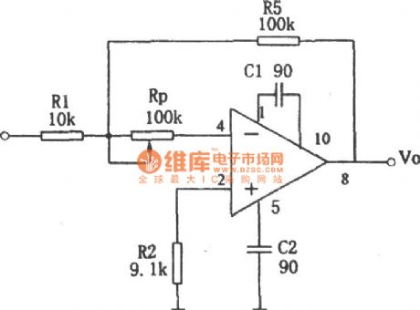
The positive and negative values gain of adjustable amplifier circuit composed of LM107
Published:2011/8/9 2:07:00 Author:Rebekka | Keyword: positive value gain , negative value gain , adjustable amplifier
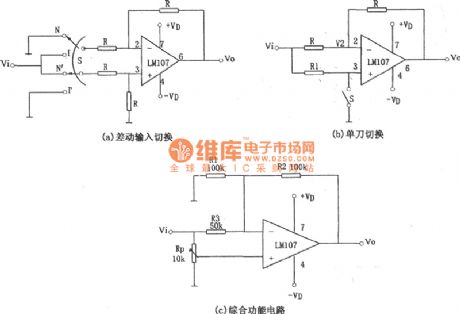


Figure (a) is the differential input switching circuit. The input end of the circuit uses a double-pole double-throw switch S to achieve positive and inverting amplification switch. It also uses four high-precision equivalent resistor R to keep the gain value. It is actually a positive and inverting voltage follower, when the S in N (ie S and the upper part of the figure the two contacts N and N 'on), the same phase follower circuit, the circuit has the following relationship: When S is placed in I and I ', the circuit has the following relationship:
(View)
View full Circuit Diagram | Comments | Reading(886)
LM4921 for dual-channel headphone amplifier typical circuit diagram
Published:2011/8/16 22:00:00 Author:Rebekka | Keyword: dual-channel headphone amplifier
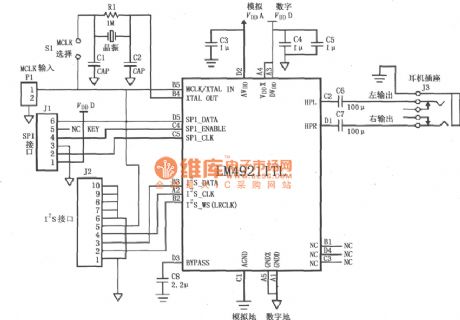
Figure shows the typical circuit of LM4921 stereo headphone amplifier. SPI interface bus J1 input controls lines signal: serial data signal SPI-DATA, serial enable signal SPI-ENABLE, serial clock signal SPI-CLK. J2 input of the I2S interface bus controls the full range of serial digital audio signal: I2S data signals I2S-DATA, I2S clock I2S-CLK. I2S word select signal I2S-WS (also known as the Right / Left Select). MCLK signal is input from P1: When S1 is off, it selects the external master clock MCLK input; when S1 is short, it uses internal oscillator (11.2896MHz).
(View)
View full Circuit Diagram | Comments | Reading(1939)
General multi-functional alarm and timer(555) circuit diagram
Published:2011/8/17 3:08:00 Author:Rebekka | Keyword: General multi-functional alarm , timer, 555
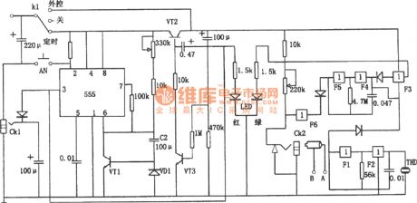
General multi-functional alarm and timer(555) circuit diagram is shown as above. The timing range of this circuit can be adjusted from 5 minutrs to 3 hours. 555 Capacitor multiplier circuit is made up of timing components C2, VD1 and VT1.For keeping K1 at timing block and press AN, 555③ pin will output high level(6~9V) and VT2 will be disconnected. When it's time to timing time, 555's pin 3 will turn to low level. CK1 will have no voltage output and VT2 will be conducted. The alarm circuit composedof F1 and F2 will produce 20 seconds alarm ,and F3 to F5 will produce light alarm. A and B ends can be added a variety of sensors to make up of an additional acoustic and optical alarm circuit. (View)
View full Circuit Diagram | Comments | Reading(1266)
M50195 Digital echo delayed application interface circuit diagram
Published:2011/8/17 3:04:00 Author:Rebekka | Keyword: Digital echo, delayed application
View full Circuit Diagram | Comments | Reading(3817)
Flat Vacuum Microelectronic flat camera tube 10×10 pixel-driven circuit diagram
Published:2011/8/17 3:02:00 Author:Rebekka | Keyword: Flat Vacuum Microelectronic, 10×10 pixel-driven, flat camera tube
View full Circuit Diagram | Comments | Reading(622)
Threshold voltage compensation analog driver circuit diagram
Published:2011/8/17 3:01:00 Author:Rebekka | Keyword: voltage compensation , threshold analog driver
View full Circuit Diagram | Comments | Reading(1035)
Voltage control drive circuit diagram with subthreshold current compensation and threshold voltage changing
Published:2011/8/17 3:00:00 Author:Rebekka | Keyword: Voltage control drive , subthreshold current compensation , threshold voltage changing
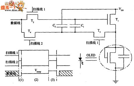
View full Circuit Diagram | Comments | Reading(792)
Optical wand amplifier circuit diagram
Published:2011/8/17 2:46:00 Author:Rebekka | Keyword: Optical wand amplifier
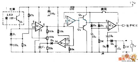
This circuit is mainly composed of light rods and four operational amplifier IC1, amplifier, and Lee silicon diode's exponential positive electrical properties can change the output of light rods into logarithmic e transformation voltage changes, its peak - peak is proportional to the white, black light currents ratio, and it has nothing to do with the absolute value. IC1b, which is the comparator, and peak detection D2-C1 clamp the output of amplifier IC1 to a fixed potential. Thus, the signal after amplification and clamping is transformed into binary digital microprocessor output. Output is compatible with TTL.
(View)
View full Circuit Diagram | Comments | Reading(793)
Impulse amplifier circuit diagram
Published:2011/8/17 3:17:00 Author:Rebekka | Keyword: Impulse amplifier
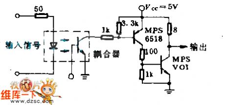
The circuit Motorola MOC 1000 optical isolator can make digital logic coupling use different supply voltages or different ground systems. At the same time, it provides almost complete isolation. The circuit can satisfy the instrumentation requirements in the transfer characteristic and have sufficient drive capability. It can be used for driving low input impedance loads. (View)
View full Circuit Diagram | Comments | Reading(1188)
Bridge structure single amplifier circuit diagram
Published:2011/8/17 3:10:00 Author:Rebekka | Keyword: Bridge structure , single amplifier
View full Circuit Diagram | Comments | Reading(859)
The separated element headphone amplifier circuit
Published:2011/8/11 22:18:00 Author:Borg | Keyword: separated element, headphone amplifier
The separated element headphone amplifier circuit is shown as above.
(View)
View full Circuit Diagram | Comments | Reading(1043)
The implanted amplifier circuit
Published:2011/8/15 23:47:00 Author: | Keyword: implanted amplifier
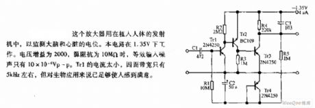
The amplifier is used in the emitter which is implanted in human bodies, so the LEV of the brain and heart can be monitored. The circuit works when the voltage is lower than 1.35V. The voltage gain is 2000, when the source impedance is 10MΩ, the equivalent input noise is only 10*10 -6Vp-p. The current of Trl is too low, so the band width is only 5kHz or so, but it is enough for biological use.
(View)
View full Circuit Diagram | Comments | Reading(922)
The long-distance body heat probe circuit
Published:2011/8/17 22:32:00 Author: | Keyword: long-distance, body heat probe
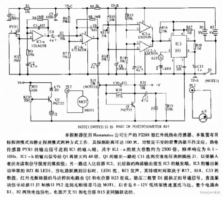
The probe is fixed with the P2288 infrared heat sensor which is produced by Hamamatsu Corp. The device has two modes which are aim detection mode and still detection mode, its detecting range is 100m and it doesn't react to the constant heat. The heat sensor PYR1 outputs signal to the input terminal of IC1, of which the magnification factor of IC1-a is about 2500, the frequency reaction is 0.1~10Hz, then the signal output by IC1-b is magnified by 40 times by Q1. The output of Q1 is sent to the outlet of AC voltmeter by C11, so the millvoltmeter can be inserted and read out the signal power value. (View)
View full Circuit Diagram | Comments | Reading(1582)
The imported USB serial switch cirucit
Published:2011/8/11 21:14:00 Author:Borg | Keyword: imported USB, serial switch cirucit
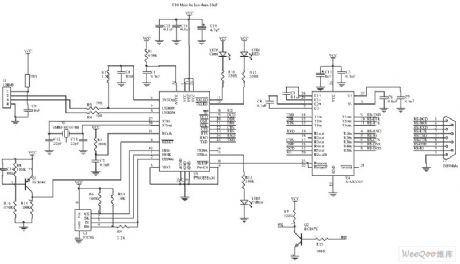
The imported USB serial switch cirucit is shown as above.
(View)
View full Circuit Diagram | Comments | Reading(799)
| Pages:63/250 At 206162636465666768697071727374757677787980Under 20 |
Circuit Categories
power supply circuit
Amplifier Circuit
Basic Circuit
LED and Light Circuit
Sensor Circuit
Signal Processing
Electrical Equipment Circuit
Control Circuit
Remote Control Circuit
A/D-D/A Converter Circuit
Audio Circuit
Measuring and Test Circuit
Communication Circuit
Computer-Related Circuit
555 Circuit
Automotive Circuit
Repairing Circuit