
Amplifier Circuit
Index 78
2_min_RAMP
Published:2009/7/13 3:58:00 Author:May
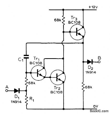
Used in multiple timer for development of photographic paper, in which six independent timers are started in sequence as each sheet of exposed paper is placed in developer. C1 is 1 μF and R1 is 11 megohms for 2-min timer having accuracy within 5 s. Article gives all other circuits required and suggests modifications to meet other needs. Output B drives meter and trigger circuit for audible alarm.Timer is started by input switch connected to A.-R. G. Wicker, Photographic Development Timer, Wireless World, April 1974, p 87-90. (View)
View full Circuit Diagram | Comments | Reading(865)
450_MC_R_F_AMPLIFIER
Published:2009/7/13 3:57:00 Author:May
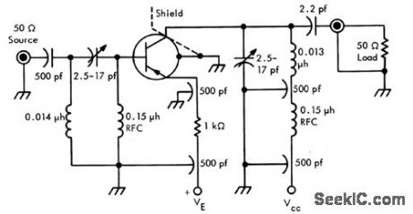
Gives averago Power gain of 8.6 db, bandwith of 48 Mc, and noise figure of 6 db Uses linear active network, designed with Linvill chart. Lead inductance was minimized by removing most of the Teflon from TO-18 socket so only thin disk, approximately chassis thickness, remains-Texas Instruments Inc., Solid-State Communcations, McGrow-Hill, NY.,1966, p 97.
(View)
View full Circuit Diagram | Comments | Reading(894)
GAIN_CONTROLLED_LOG_AMPLIFIER
Published:2009/7/13 3:56:00 Author:May
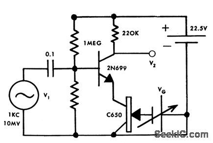
Based on fact that gain of common-emitter fet stage is almost inversely proportional to emitter resistance, and resistance of let operating below cutoff is linear function of grid voltage. Can be used as agc amplifer and as multiplier.-Y. J. Lubkin, Gain Controlled Log Ampliler, GEE, 10:9, p 91. (View)
View full Circuit Diagram | Comments | Reading(929)
GATEDBEAM_SQUAREWAVE_GENERATOR
Published:2009/7/16 4:04:00 Author:Jessie
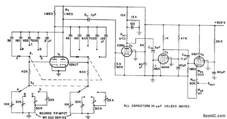
Amplifies without attenuation up to tenth harmonic of square-wave fundamental, from which output of 50 to 500,000 pps can be adjusted over desirable range without wave form distortion. Uses twin-triode 12AU7 as symmetrical mvbr, 6BN6 as gated-beam tube, 6AN6 as wideband amplifier, and 6AG7 as cathode-follower output. Operating frequencies are changed by S1 and S2. R27 adjusts output signal level from 0.8 to 8 v peak to peak. Rise time for 500-kc signal is better than 0.07 microsec. Provides 5 distinct repetition rates (50, 1,000, l0,000,100,000, and 500,000 pps) for checking amplifiers up to at least tenth harmonic of fundamental repetition ratio.-Gated-Beam Tube Square-Wave Generator, Electronic Circuit Design Handbook, Mactier Pub. Corp., N.Y., 1965, p 175. (View)
View full Circuit Diagram | Comments | Reading(2295)
60_MC_AMPLIFIER
Published:2009/7/13 3:44:00 Author:May
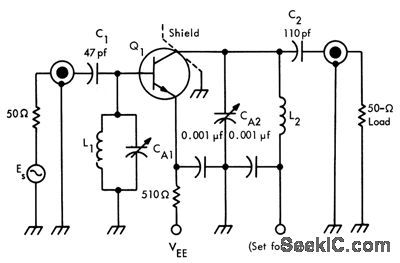
Design equations are given and example worked out for 10-Mc band-width at 60 Mc and gain of 11.5 db, using 2N743. L1 is 1.5 turns of No. 14 wire and L2 is 2 turns, both 0.25 inch in dicmeler. VEE is 5 v.-Texas Instruments Inc., Solid.State Communications, McGraw-Hill, N.Y., 1966, p 87. (View)
View full Circuit Diagram | Comments | Reading(753)
RINGING_TYPE_PULSE_GENERATOR
Published:2009/7/16 4:02:00 Author:Jessie
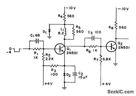
Used in some large high-speed computers to transmit pulses from central unit over long distances as d-c levels, then convert back to pulse forms. To convert level back to pulse, transistor switch is fumed off by positive-going wave front energizing ringing circuit. Input triggering of ringing stage is accomplished when definite threshold level is exceeded.-Pulse Generator for High-Speed Computers, Electronic Circuit Design Handbook, Mactier Pub. Corp., N.Y., 1965, p 75. (View)
View full Circuit Diagram | Comments | Reading(867)
HIGH_GAIN_AMPLIFIER
Published:2009/7/16 4:01:00 Author:Jessie
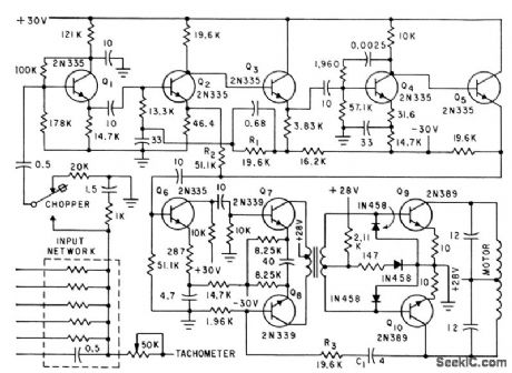
Integrator amplifier using ten silicon transistors in five voltage gain stages gives gain of 250,000. To prevent saturation by spurious microvolt signals, input network is shielded by Mu-metal can grounded to signal ground and overall steel can grounded to power ground. Power supply ripple must be below 0.01%. Amplifier drives 6.w ac servomotor having d-c tachometer on same shaft.-S. T. Cop and N. P. White, Guidance Systems in Manned Space Flight, Electronics, 32:33, p 49-51. (View)
View full Circuit Diagram | Comments | Reading(0)
OUTPUT_BUFFER_AMPLIFIER
Published:2009/7/16 4:00:00 Author:Jessie
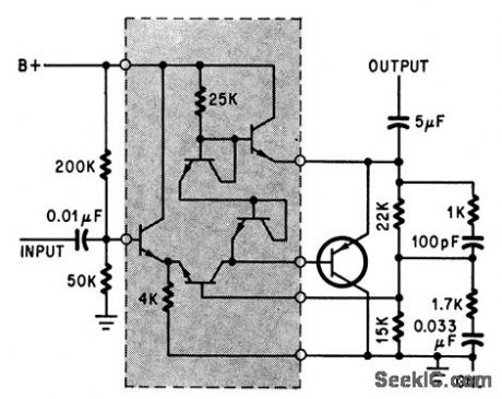
Integrated construction (shaded) is used with external pnp transistor.-D. D. Robinson, linear Microcircuits Scarce? Now You Can Breadboard Your Own, Electronics, 37:27, p 58-64. (View)
View full Circuit Diagram | Comments | Reading(944)
OP_AMP_ANTENNA_AMPLIFIER
Published:2009/7/13 3:30:00 Author:May
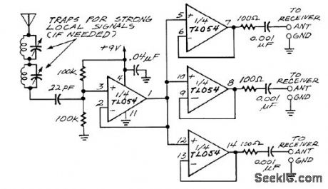
The impedance of a random-wire antenna at broadcast-band frequencies will be several kilohms, a poor match for the 50-Ω input of a receiver. Also, the inputs of multiple receivers can't be connected directly to a single antenna, or they'll detune each other. The circuit solves both problems. The first op amp overcomes the impedance mismatch, strengthening the signal greatly even though it has no voltage gain. The rest of the op amps feed the signals to the separate receivers. No low-pass filter is needed because the gain of these op amps drops off sharply above 2 or 3 MHz. (View)
View full Circuit Diagram | Comments | Reading(1495)
SIMPLE_LAMP_DRIVER
Published:2009/7/13 3:30:00 Author:May
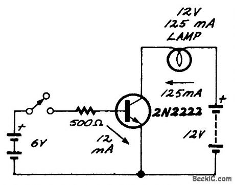
Small current through the base controls large current through the collector.Close the switch,and the bulb lights. (View)
View full Circuit Diagram | Comments | Reading(857)
D_C_OPERATIONAL_AMPLIFIER
Published:2009/7/16 3:58:00 Author:Jessie
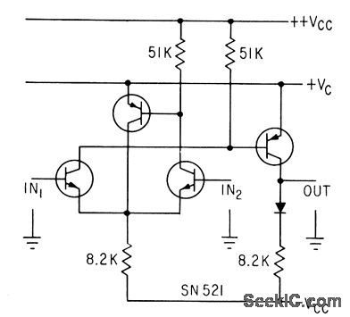
Open-loop voltage gain is 62 db, input impedance is 18,000 ohms differential and 10,000 ohms to ground, and output impedance is 8,000 ohms.-Operational Amplifiers are Getting Smaller, Electronics, 35:52, p 66. (View)
View full Circuit Diagram | Comments | Reading(819)
FINGERTIP_SIZE_SERVO_AMPLIFIER
Published:2009/7/16 3:58:00 Author:Jessie


Direct-coupled class A servo amplifier diffused into 0.75-inch.diameter silicon wafer gives power output of 1.5 w and overall closed-loop gain of 200. Distributed diode planes are introduced by substrate,-M. W. Aarons, Putting a Servo Amplifier on a Small Silicon Wafer, Electronics, 35:52, p 33-35. (View)
View full Circuit Diagram | Comments | Reading(793)
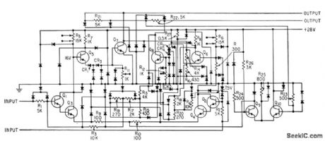
AUDIO_POWER_AMPLIFIER
Published:2009/7/16 3:56:00 Author:Jessie
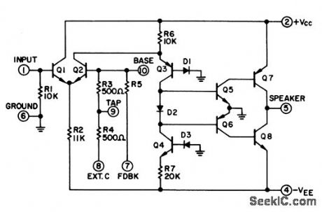
MC1524 chip gives high efficiency, low distortion, and wide range along with highest output power per mitted by dissipation of TO-5 case. Chip is combined with superior power-handling of standard bottom-collector output transistors to give monobrid amplifier providing 1 w to speaker. True class-B output circuitry gives low standby current, with crossover distortion of class B minimized by using current source Q3-Q4 for quad Q5-Q6-Q7-Q8. Diode D2 further reduces crossover distortion.-R. A. Hirschfeld, Audio Power Applications Using Integrated Circuits, Motorola Application Note AN-162, Aug. 1965. (View)
View full Circuit Diagram | Comments | Reading(0)
AUDIO_AMPLIFIER
Published:2009/7/13 3:06:00 Author:May
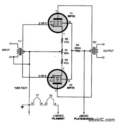
Some hobbyists still prefer to use older vacuum tube technology. A push-pull audio amplifier using a pair of 60FX5 tubes is shown in the figure. T1 is a 1:3 audio interstage, while T2 is a universal output transformer of about 5000 Ω to voice coil (4 or 8 Ω) impedance. (View)
View full Circuit Diagram | Comments | Reading(0)
VOLTAGE_CONTROLLED_AMPLIFIER_STAGE
Published:2009/7/13 3:05:00 Author:May
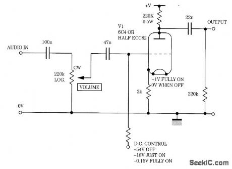
Gain is controlled by a variable negative grid bias in this amplifier stage. (View)
View full Circuit Diagram | Comments | Reading(788)
SINGLE_ENDED_HI_Fl_AMPLIFIER
Published:2009/7/13 3:04:00 Author:May
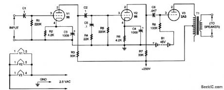
The circuit as shown will handle up to about 0.5 V; above that, distortion will be present. The input stage amplifies the signal voltage about seven times, and the second stage amplifies the voltage about 10 times. Both stages use type 56 triodes (V1 and V2). The output stage uses a type 2A3 tube, V3. Two 22.5-V batteries wired in series (B1) were used to provide 45 V on the grid of V3. In this circuit (and other single-ended amplifiers), direct current flows in the primary of the output transformer (T1) to use the circuit modification shown in Fig. 2. That change keeps dc out of the primary at some sacrifice in power. With the modification, the amplifier will be flat (within 1 dB) from 20 to 20,000 Hz. (The modified circuit requires that a high-voltage transformer be used in the power-supply circuit.) Note that transformer T1 is shown connected from one end of the primary to the center tap. That was done because it is assumed that the transformer used will have a primary impedance of about 8000 Ω. The recommended load for a 2A3 tube (V3) is 2500 Ω for maximum output, but increasing the impedance lowers the distortion while only slightly lowering the power. (View)
View full Circuit Diagram | Comments | Reading(890)
SIMPLE_MMIC_AMPLIFIER_CIRCUIT
Published:2009/7/13 3:03:00 Author:May
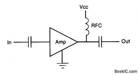
This is the simplest implementation of an MMIC amplifier. (View)
View full Circuit Diagram | Comments | Reading(660)
MMIC_AMPLIFIER_CIRCUIT
Published:2009/7/13 3:02:00 Author:May
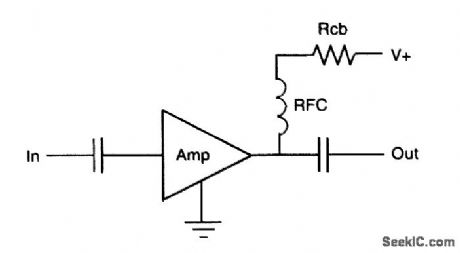
The addition of a series dropping resistor allows operation at higher supply voltages. (View)
View full Circuit Diagram | Comments | Reading(758)
CASCADED_MMIC_AMPLIFIER_CIRCUIT
Published:2009/7/13 3:01:00 Author:May
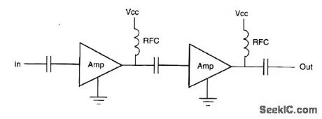
Most MMIC amplifliers can be cascaded, with dc blocking as the only interstage connection requirement. (View)
View full Circuit Diagram | Comments | Reading(1622)
COMBINED_MMIC_AMPLIFIERS
Published:2009/7/13 3:00:00 Author:May
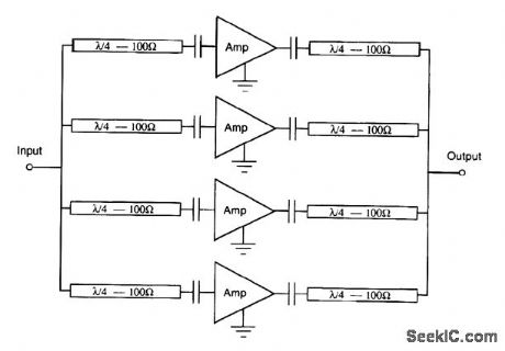
Quadrature combining, practical in microstrip, can be used to obtain a medium power output from several MMIC amplifiers. (View)
View full Circuit Diagram | Comments | Reading(834)
| Pages:78/250 At 206162636465666768697071727374757677787980Under 20 |
Circuit Categories
power supply circuit
Amplifier Circuit
Basic Circuit
LED and Light Circuit
Sensor Circuit
Signal Processing
Electrical Equipment Circuit
Control Circuit
Remote Control Circuit
A/D-D/A Converter Circuit
Audio Circuit
Measuring and Test Circuit
Communication Circuit
Computer-Related Circuit
555 Circuit
Automotive Circuit
Repairing Circuit