
Amplifier Circuit
Index 64
The USB multimedia 2.5W+2.5W voice box design circuit
Published:2011/8/11 21:17:00 Author:Borg | Keyword: multimedia, voice box, design circuit
The USB multimedia 2.5W+2.5W voice box design circuit is shown as above.
(View)
View full Circuit Diagram | Comments | Reading(989)
The USB mouse design circuit
Published:2011/8/11 21:18:00 Author:Borg | Keyword: USB mouse, design circuit
The USB mouse design circuit is shown as above.
(View)
View full Circuit Diagram | Comments | Reading(1778)
Direct Driving Circuit
Published:2011/8/13 7:35:00 Author:Robert | Keyword: Direct, Driving
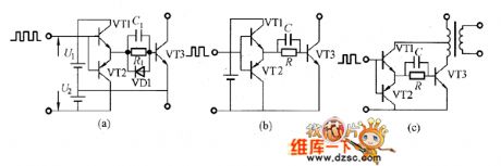
The most effective method to add reverse bias voltage is using the circuit in picture (a). In this circuit when the switch transistor VT3 is disconnected, the VT2 would be conducted and add the reverse voltage to the switch transistor VT3's base electrode. Even the pulse is narrow it could add enough reverse bias voltage. But it needs the reverse bias power U2. The VT2's power is using the circuit in picture (c). It could get the voltage U2 from the transformer tapping.
The picture shows the direct driving circuit. (View)
View full Circuit Diagram | Comments | Reading(728)
The flashlight drive circuit
Published:2011/8/18 7:57:00 Author: | Keyword: flashlight drive
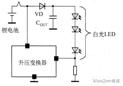
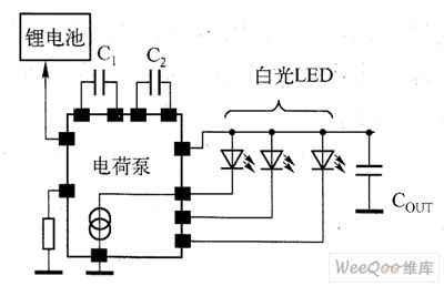
The electric charge is fixed with capacitors as the storage elements, and it doesn't need any external inductors, so the electromagnetic disturbance problem doesn't exist. Besides, the whole resolution takes little PCB coverage, but the efficiency is low. As the flashlight working time is short, which is about 100~300ms, so its efficiency has little effect on the battery lifespan. In figure 2 is the application circuit of the electric charge pump standard white light LED.
Figure 1 the application circuit of the inductance boost transformer drive standard white light LED
(View)
View full Circuit Diagram | Comments | Reading(944)
The electron tube crossing balance inverting phase circuit
Published:2011/8/11 21:53:00 Author:Borg | Keyword: electron tube, crossing balance, inverting phase
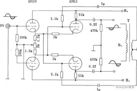
The electron tube crossing balance inverting phase circuit is also called Zell inverting phase circuit, in which 6N10 and 611 can be used as the pre-amplifier and phase inverter, and the circuit can be connected with the rear-end power amplifier tube installed with 300B.
(View)
View full Circuit Diagram | Comments | Reading(1587)
The high speed phase inverting amplifier circuit
Published:2011/8/11 21:54:00 Author:Borg | Keyword: high speed, phase inverting amplifier
The high speed phase inverting amplifier circuit is shown in the figure.
(View)
View full Circuit Diagram | Comments | Reading(799)
The winking kitten circuit
Published:2011/8/15 20:55:00 Author: | Keyword: winking kitten
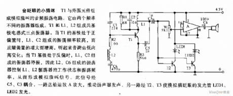
The winking kitten circuitT1 and the external elements form an audio oscillating circuit which can simulate the sound of mew. T1, L1 and L2 form the common base inducting 3-terminal oscillator. When the base electrode of T1 is biased, the oscillating frequency of L1 and C2 is high, and it rises with the increasing of the bias, it sounds the tune rises up from low. When the base electrode of T1 is in the backward bias, the oscillator composed of L1 and C2 stops, therefore, the oscillator composed of L2 and C6 controls the working state and oscillating frequency of the oscillator consists of L1 and L2, so the sound of mew is simulated.
(View)
View full Circuit Diagram | Comments | Reading(746)
The stereo toy car circuit
Published:2011/8/15 21:05:00 Author: | Keyword: stereo, toy car
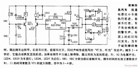
The stereo toy car circuit After the power is on, the toy car is running forward, the front light is glowing, the car is making the police car sound, and the red light on the top of the car is flashing; when the car is touching the obstacle, it is making a turn and backing off, the rear light is glowing, the front light is put off, at the same time, the sound is changed into sweet ding-dong, ding-dong dual sound. After it is backing off for 3~4s, it will run forward again automatically; if it touches the obstacle while backing off, it will change the route and run forward immediately.
(View)
View full Circuit Diagram | Comments | Reading(1106)
The light chasing beetle circuit
Published:2011/8/15 21:16:00 Author: | Keyword: light chasing, beetle
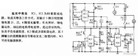
The light chasing beetle circuit Both IC1 and IC2 are the time-based integrated circuits, and they are fixed in the non-steady working state. The 3 pin output by it control relay J1, J2 and J3 respectively, the 4-pin is linked with the LST. When there is light, the relay is working, and the relative motor is running, with the help of the driving gear, the toy beetle is going forward. IC3 is a multi-resonance oscillator circuit, whose 3-pin outputs the low oscillating signal which drives the LED to flash, W3 can change the oscillating frequency.
(View)
View full Circuit Diagram | Comments | Reading(897)
Voice switching and amplifier schematic diagram
Published:2011/8/11 1:43:00 Author:Ecco | Keyword: Voice switching , amplifier
View full Circuit Diagram | Comments | Reading(979)
MAX4295, MAX4297 high-efficient Class-D audio amplifier circuit diagram
Published:2011/8/14 21:38:00 Author:Ecco | Keyword: high-efficient, Class-D audio amplifier
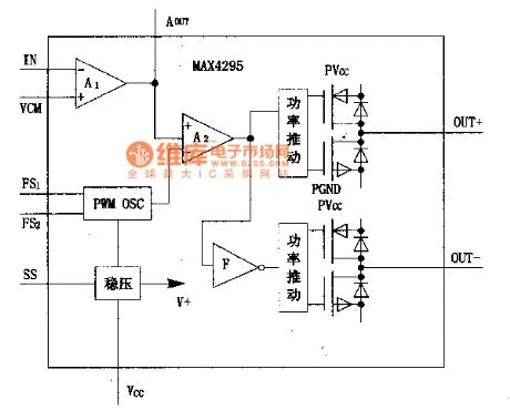
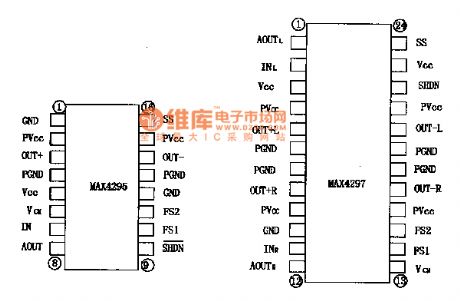
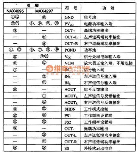
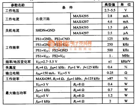
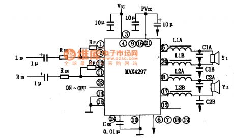
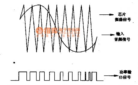
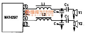
MAX4295 and MAX4297 are the latest switching (D class) audio amplifiers produced by U.S. MAXIM (Maxim), and it is widely used in pronunciation electronic products, such as walkman notebook computers, music cards, mobile phones and other battery-powered electrical products, and you can maximize battery life. 1. The internal block diagram and pin functions The MAX4295 is a mono amplifier, MAX4295 is the dual-channel amplifier. It is composed of the voltage reference, input buffer amplifier, oscillator, PWM modulator, power driver and MOSFET and other components.
(View)
View full Circuit Diagram | Comments | Reading(1484)
High-voltage amplifier circuit diagram for piezoelectric ceramic element
Published:2011/8/14 22:22:00 Author:Ecco | Keyword: High-voltage amplifier, piezoelectric ceramic element
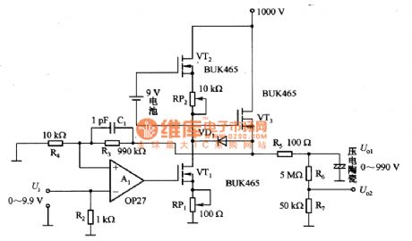
Figure 1 shows the high-voltage amplifier for piezoelectric ceramic element. Piezoelectric ceramic element is an excellent location converter, which is widely used in micrometer and so on. Piezoelectric ceramic element has the maximum elongation in 2OkV / magnitude electric field with typical value in 0.1%, so here needs to use high-voltage amplifier. This is a simple, low-cost 1000V high-voltage amplifier. Piezoelectric ceramic element is used as the amplifier load. High-voltage amplifier consists of three high-voltage MOSFET (BUK465) and a low-noise operational amplifier (0P27) and so on.
(View)
View full Circuit Diagram | Comments | Reading(6900)
Differential amplifier circuit diagram with 20MHZ bandwidth
Published:2011/8/11 22:30:00 Author:Ecco | Keyword: Differential amplifier, 20MHZ bandwidth
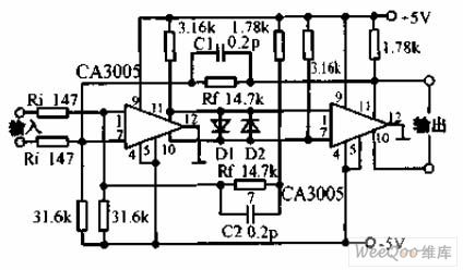
The circuit consists of two CA3005 RF amplifiers, the gain is decided by the ratio Rr / Ri. Capacitors C1, C2 are used to improve the bandwidth to prevent high-frequency self-excitation. Error of resistors is 1%, and the bandwidth is 200MHz, and time delay is 20μs.
(View)
View full Circuit Diagram | Comments | Reading(997)
Voltage-controlled gain amplifier circuit diagram
Published:2011/8/11 22:33:00 Author:Ecco | Keyword: Voltage-controlled, gain amplifier
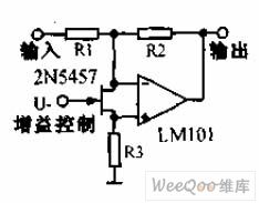
1.53 voltage-controlled gain amplifier is connected to the FET input op amp between the two input ends, and it is used as a voltage-controlled resistor, the resistance changes linearly with the voltage, and the changing range is ten times square, and it has excellent control characteristics. The resistance depends on the op amp.
(View)
View full Circuit Diagram | Comments | Reading(1067)
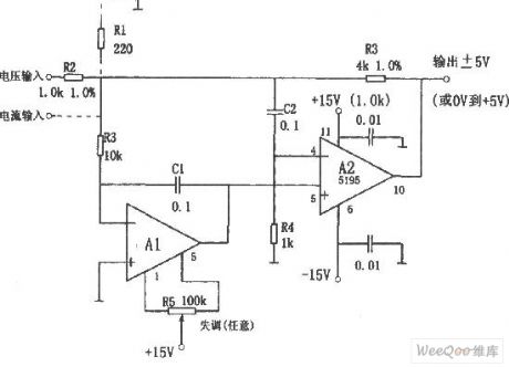
Adjustable voltage-stabilizing voltage circuit diagram
Published:2011/8/9 18:29:00 Author:Vicky | Keyword: Adjustable voltage-stabilizing voltage

The circuit is a adjustable voltage-stabilizing circuit of the output voltage. Integrated operational amplifier works as voltage follower. When the potentiometer RP slides to the lowest end, U1min = (R1+RP+R2)/ (RP+R1) ·U23;when it slides to the top end, U1max = (R1+RP+R2/R1· U23.
Therefore, the output voltage can be adjusted by sliding the RP. (View)
View full Circuit Diagram | Comments | Reading(818)
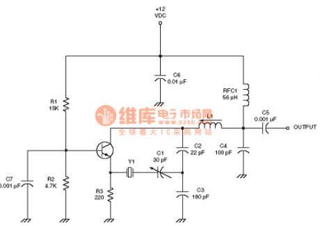
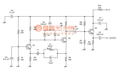
the Oscillator circuit of the radio frequency :Butler oscillator RF circuit
Published:2011/8/12 22:09:00 Author:Ariel Wang | Keyword: Oscillator, radio frequency , Butler

View full Circuit Diagram | Comments | Reading(1045)
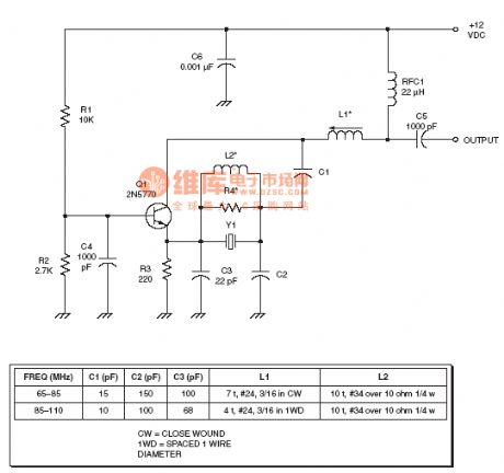
the Oscillator circuit of the radio frequency :Butler overtone crystal oscillator RF circuit
Published:2011/8/12 22:30:00 Author:Ariel Wang | Keyword: oscillator, radio frequency , Butler, overtone, crystal
View full Circuit Diagram | Comments | Reading(1557)
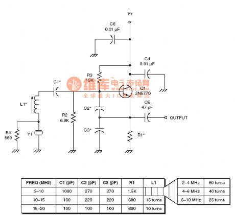
the oscillator circuit of the radio frequency :Higher overtone crystal oscillator RF circuit
Published:2011/8/12 22:32:00 Author:Ariel Wang | Keyword: oscillator, Higher overtone, crystal , RF
View full Circuit Diagram | Comments | Reading(944)
the Oscillator circuit of the radio frequency :Impedance inverting colpitts crystal oscillator RF circuit
Published:2011/8/12 22:35:00 Author:Ariel Wang | Keyword: oscillator, Impedance, inverting, colpitts, crystal, RF
View full Circuit Diagram | Comments | Reading(1565)
the oscillator circuit of the radio frequency :Improved Butler oscillator RF circuit
Published:2011/8/13 0:29:00 Author:Ariel Wang | Keyword: oscillator, radio frequency , Improved, Butler
View full Circuit Diagram | Comments | Reading(1341)
| Pages:64/250 At 206162636465666768697071727374757677787980Under 20 |
Circuit Categories
power supply circuit
Amplifier Circuit
Basic Circuit
LED and Light Circuit
Sensor Circuit
Signal Processing
Electrical Equipment Circuit
Control Circuit
Remote Control Circuit
A/D-D/A Converter Circuit
Audio Circuit
Measuring and Test Circuit
Communication Circuit
Computer-Related Circuit
555 Circuit
Automotive Circuit
Repairing Circuit