
Amplifier Circuit
Index 66
Capacitive Switch Circuit
Published:2011/8/2 1:30:00 Author:Joyce | Keyword: Capacitive , Switch
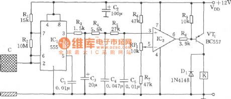
As shown in the figure, the switch circuit is composed of capacitive oscillator, integrating network, comparative circuit and relay control circuit. When the human body gets close to the metal plate, inductive capacitance over the ground will increase, so that the astable multivibrator formed of 555 will start oscillation or have its oscillation frequency changed. The output alternating square wave will be added to the inphase end of comparator IC2 (LM324) after going through the three-level integrating network to be compared with the reference voltage which has been set. Then it will output a transitioning negative pulse, VT1 will break over, and K will actuate to connect the load circuit. Conversely, the load circuit will be disconnected. Selection of the induction plate should make oscillation frequency be no less than several thousand kHz. (View)
View full Circuit Diagram | Comments | Reading(2389)
The CMOS logic probe circuit
Published:2011/7/18 6:35:00 Author:Christina | Keyword: CMOS, logic probe
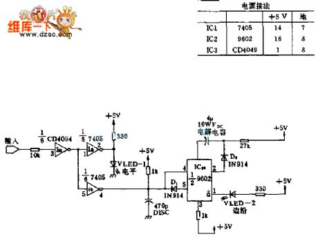
This circuit is the fault diagnosis tool, you need to connect it to the microprocessor to display the state of important port. When the TTL input is 1 , the LED turns on; when the TTL input is 0 , the LED will not turn on. When the input is from 1 to 0 or 0 to 1 , the edge LED-2 turns on just one time. The input port uses the CMOS inverting buffer 3a to prevent the probe affects the work of microprocessor.
(View)
View full Circuit Diagram | Comments | Reading(1429)
The circuit of the differential amplifier
Published:2011/7/18 6:36:00 Author:Christina | Keyword: Differential amplifier
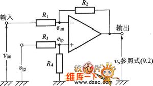
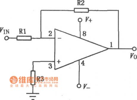
The Differential amplifier circuit is as shown:
(View)
View full Circuit Diagram | Comments | Reading(778)
GL3274 (TV) infrared remote control receiving preamplifier circuit
Published:2011/8/4 1:28:00 Author:Christina | Keyword: TV, infrared, remote control, receiving, preamplifier circuit
The GL3274 has the same functions and pin arrangement with the CX20106A, so they can exchange directly. The technical characteristics, absolute maximum ratings, main electrical specifications, logic diagram and typical application circuits of GL3274 can reference the CX20106A's.
(View)
View full Circuit Diagram | Comments | Reading(792)
Instrumentation Amplifier (OP08) Circuit With Differencial Input Pre-Amplifier
Published:2011/8/3 20:26:00 Author:Robert | Keyword: Instrumentation, Amplifier, Differencial, Input, Pre-Amplifier
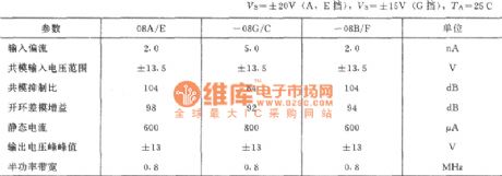
For the instrumentation amplifier of electronic measuring circuit, its input signal's amplitude peak may usually be a few mV. But the common-mode noise voltage level could be as high as a few volts. So the instrumentation amplifier's input drift, noise rejection and common-mode rejection ratio is significant for the amplifier's dynamic performance. At the same time the measured source's internal resistance could not be controlled. And the signal internal resistance's variation could make the amplifier's resistors mismatch, which connect respectively from the two input ports to ground. This mismatch could cause not only the change of the gain, but also cause the common-mode rejection ratio decreasing.
(View)
View full Circuit Diagram | Comments | Reading(759)
Single-Port Input Into Differencial Input Feeder Line Driver (OPA2604 And BUF634) Circuit
Published:2011/8/7 21:58:00 Author:Robert | Keyword: Single-Port, Input, Differencial, Feeder Line, Driver
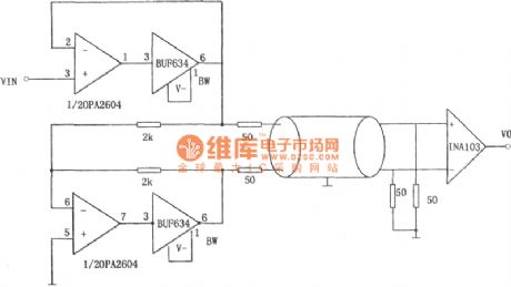
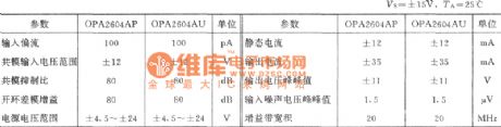
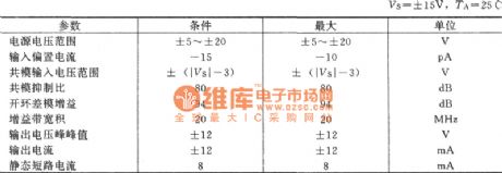
The picture shows the single-port input into differencial input feeder line driver. The circuit uses 4 different integrated operational amplifiers: high-fidelity dual operational amplifiers OPA2604, which is a FET input type operational amplifier; two 250mA high-speed buffer BUF634, which is working in wide-band mode (the pin 1 should be connected to the negative power port which is pin 4), that means its band width is extended to about 180MHz, and in this case the BUF634's voltage magnification is 1; also a INA103 operational amplifier, which is a instrument amplifier with low noise and low distortion. If necessary, it could also use the INA101 to replace the INA103.
The integrated dual operational amplifiers OPA2604's main parameters (typical value) are shown in the picture 2. (View)
View full Circuit Diagram | Comments | Reading(1314)
μPC2002 9W Audio Power Amplifier Circuit
Published:2011/7/18 9:27:00 Author:Robert | Keyword: 9W, Audio, Power, Amplifier
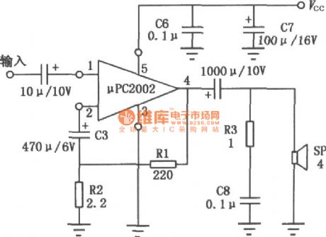
The μPC2002 is a audio power amplification IC which uses 5-pin single inline plastic package. It can be divided to H type and V type according to the shape of its lead wire. This circuit has a large output power and low distortion and low noise. It also has the low impact sound when starting.The circuithasprotection circuits for power surge, over voltage and load's short circuit and so on. So it is widely used in car stereo radio and used as audio power amplifier in videocorder. Its typical application circuit is shown in the picture. (View)
View full Circuit Diagram | Comments | Reading(2175)
50W Hi-Fi Audio Integrated Power Amplifier Circuit Composed Of TDA1514A
Published:2011/7/17 22:09:00 Author:Robert | Keyword: 50W, Hi-Fi, Audio, Integrated, Power Amplifier
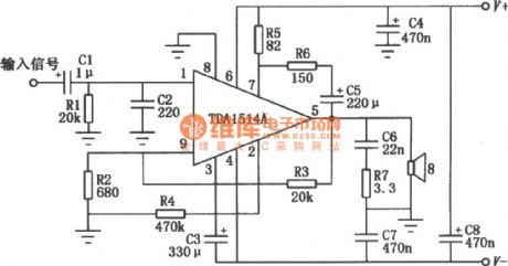
The picture shows the audio integrated power amplifier. It's the typical application circuit composed of TDA1514A. TDA1514A is a 50W Hi-Fi audio amplification IC produced by the Philips company. Its internal protection circuitsare complete which means it has not only the general over-heating, output short circuit protection, but also the safe operating area protection. The circuit is also set up a silent switch to suppress the starting noise' appearance. In the circuit's design it is also considered the better ripple rejection and low offset with low thermal resistance. (View)
View full Circuit Diagram | Comments | Reading(3193)
50W Hi-Fi Integrated Audio Power Amplifier (TDA1514A) Circuit
Published:2011/7/17 22:09:00 Author:Robert | Keyword: 50W, Hi-Fi, Integrated, Audio, Power Amplifier
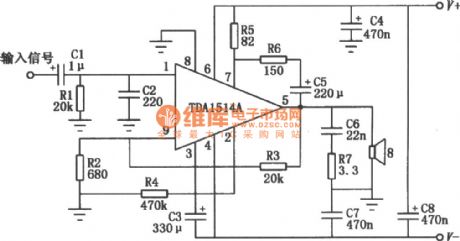
The picture shows the audio integrated power amplifier's typical application circuit composed ofTDA1514A. TDA1514A is a 50W Hi-Fi audio amplification IC produced by the Philips company. Its internal protection circuitsare complete, which means it has not only the general over-heating, output short circuit protection, but also the safe operating area protection. The circuit is also set up a silent switch to suppress the starting noise' appearance. In the circuit's design it is also considered the better ripple rejection and low offset with low thermal resistance. (View)
View full Circuit Diagram | Comments | Reading(5663)
Computer Microphone and JFET-MOSFET earphone power amplifier circuit diagram
Published:2011/8/8 0:23:00 Author:Sophia | Keyword: Computer Microphone, JFET-MOSFET earphone, power amplifier
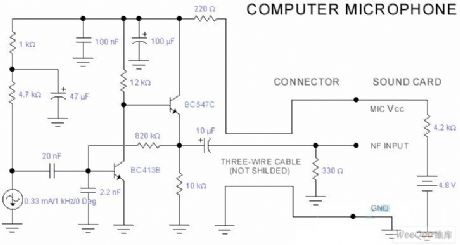
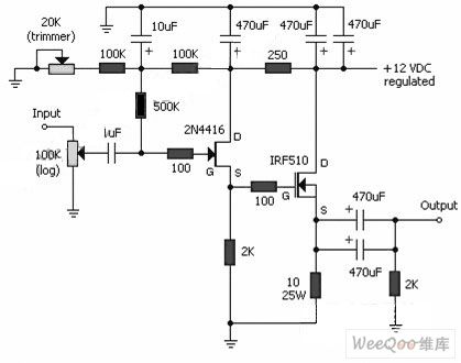
PC sound card usually possesses microphone input and loudspeaker output, sometimes line input and output. The design of input resistance of dynamic microphone just can be achieved in the scope of 200~600ohms. Sound card can use a common electret microphone to suit this curcuit. a composite amplifier can use two transistor.
when BC413B is working normally, it slightly drives the microphone signal emitter amplifier, next, it comes to the stage of emitter follower, which is necessary. Because that the microphone, curcuit and battery make use of the distance of some sound card, the low output resistance of circuit and shielded cable can ensure to collect the clean signal through the smallest noise pickup. (View)
View full Circuit Diagram | Comments | Reading(2809)
The 3-channel audio power amplifier ICTA18H circuit
Published:2011/8/1 3:09:00 Author:Seven | Keyword: 3-channel, audio power amplifier

The IC working voltage is 10-30V. The limit output power is 50W(when the power supply is 20V and the impedance of the loudspeaker is 8Ω, there is 6W output power without any distortion). Figure 1 is the typical application of TA8218H. In the affiliated table are the pin functions and the tested data on Toshiba 2938XP(with Hangzhou U-201 multimeter, the R*100 gear). By the way, either of TA8218AH or TA8218AN can replace TA8218H.Figure 1. the typical application of TA8218H
(View)
View full Circuit Diagram | Comments | Reading(1826)
The driving circuit of proportional electromagnet
Published:2011/7/15 21:50:00 Author:Ariel Wang | Keyword: driving, proportional electromagnet
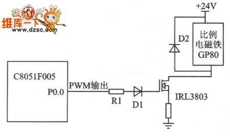
If you want to control the circuit,you can change duty ratio which is input to electrical signal of proportional electromagnet switch to realize controlling electric current. The more place the duty ration takes ,the faster of the controlling electric current goes through the coil of electromagnet.And the larger of the displacement . See chart 1 for the proportional electromagnet driveing circuit.
In driving circuit,R1 is current limiting resistor .It conducts IRL tube.D1 is a steering diode. It provides the right voltage direction for IRL3803 tube. Diode D2 is being the protective role.It avoids over voltage destroy proportional electromagnet.Proportional electromagnet is charged directly by 24V voltage.
(View)
View full Circuit Diagram | Comments | Reading(862)
the circuit of improved series resonant converter
Published:2011/7/15 21:45:00 Author:Ariel Wang | Keyword: improved, series, resonant, converter
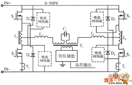
If y (View)
View full Circuit Diagram | Comments | Reading(816)
The circuit of ICS1523 typical application
Published:2011/7/15 21:52:00 Author:Ariel Wang | Keyword: The circuit of ICS1523s typical application
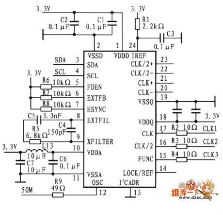
The circuit of ICS1523's typical application is as the chart below.The circuit is monitor controller of SID13806 type.It provides synchronous video signals.The signals are needed when SID13806 connects LCD.ICS1523 inputs 50 MHz (pin 12) .It outputs CLK1(pin 25).CLK2(12.5MHz) and CLK3(387.6kHz) are connected to S1D13806's BUSCLKA (pin 60),CLK1(pin 66),CLK12(PIN 64) and CLK13(pin).
(View)
View full Circuit Diagram | Comments | Reading(723)
Ordinary low-noise broadband amplifier circuit diagram
Published:2011/8/2 2:40:00 Author:Rebekka | Keyword: Ordinary low-noise, broadband amplifier
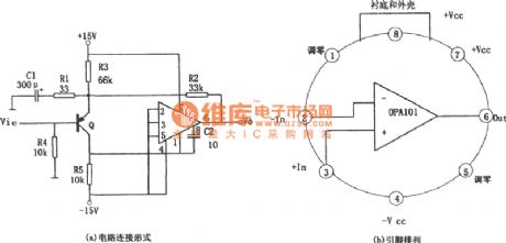
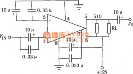
The gain bandwidth of some integrated amplifier is small (about l ~ 2 MHz), the input noise is high and the conversion rate is low pressure (about 0.5 V/u s). The reason why the gain bandwidth is small is that the operational amplifier internal input class level shift from the transistor phase shift. Conversion rate is low, because the input stage emitter current is too small. Figure (a) shows the low noise amplifier broadband circuit composed of the application ordinary op-amp integrated chips OPA101. The circuit can increase the convert rate to 30 times, and its gain bandwidth can be close to l00MHz.
(View)
View full Circuit Diagram | Comments | Reading(965)
F1590 single supply with AGC wideband single op amp circuit diagram
Published:2011/8/4 21:21:00 Author:Rebekka | Keyword: Single Supply, AGC wideband , single op amp
F1590 and the United States Motorola MC1590 are similar and they have the same parameters. It uses double-ended input, double-ended output and AGC end. It also has the features of a high gain, frequency bandwidth, automatic gain control etc. - Iffi airborne radar communication, navigation receivers, video amplification, electronically controlled attenuator, mixer and so on. The typical application circuit is shown as above. (View)
View full Circuit Diagram | Comments | Reading(1911)
Non-inverting type ideal diode circuit formed by the OP amplifier
Published:2011/8/7 3:32:00 Author:Sophia | Keyword: Non-inverting type, ideal diode circuit, OP amplifier
Rectifier power supply circuit is indispensable one of the power supply circuits, even if except the power supply circuit, it is also often used in measuring how the current (AC) signal is converted into direct current (DC). But when high-precision AC to DC conversion is carried out, there is a problem caused by the diode forward voltage VF, that the temperature coefficient of the insensitive zone and VF is about-2mV / ℃. Therefore, the high-precision AC to DC conversion is necessary, OP amplifier would be a common element, meanwhile the diode is inserted in the feedback loop, which is ideal diode circuit. (View)
View full Circuit Diagram | Comments | Reading(1356)
The full-wave rectification circuit with the absolute value of the idealized diode
Published:2011/8/7 2:46:00 Author:Sophia | Keyword: The full-wave rectification circuit, idealized diode, absolute value

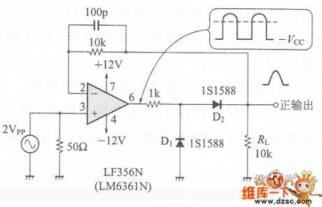
Figure 1 is the absolute value circuit of the amplifier OP often mentioned on a good textbook, that is full-wave rectifier circuit. Circuit is constituted of half-wave rectifier circuit A1 and the addition circuit A2(for the subtraction operation when the sign is oppositive ) with OP amplifiers ideal diode.In this circuit when the input is positive half cycle, diode D1 turns on, the circuit will output the negative half-wave rectified wave. This signal adds input signal (R2 = 0.5R1 is necessary), which get a positive output.
When the input is negative, diode D2 is not conducting, and inverting amplifier composed of the resistance R1, R3 begans to move.
(View)
View full Circuit Diagram | Comments | Reading(2344)
BA4558 single power supply universal dual op amp circuit diagram
Published:2011/8/4 20:52:00 Author:Rebekka | Keyword: single power supply universal, dual op amp circuit
BA4558 is high-performance dual operational amplifier. It does not need to connect frequency compensation components. The features of the circuit are: Short circuit protection, zero offset voltage capability, low power consumption, non-blocking phenomenon, difference module and common module input voltage range. Its similar or direct substitution models are: AN45588, CA1458E, CF158MT, CF258LT, CF358CT, HAl7558PC, LA6458, LMl58, tzPC4558C and so on. The typical application circuit is shown as above. (View)
View full Circuit Diagram | Comments | Reading(4010)
Op amp zeroing circuit diagram
Published:2011/8/4 21:23:00 Author:Rebekka | Keyword: Op amp zeroing
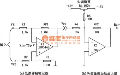
Precision op amp without changing the drift of the offset nulling circuit is shown in Figure (a) and (b). Figure (a) is low-drift precision op amp. Figure (b) is the zero offset adder circuit. According to the figure (b), when R4 = RF2, Av2 = 1, thatis the follower. Figure (a), if R1 = R2 = 1kΩ, R3 = RF1 = 1MΩ, then Vol = R3 / (R2 + R3) · (1 + RFl / Rl) · Vi2-RFl/Rl · Vil. Al's voltage gain is obviously great, so its output voltage will contain the A1 offset voltage. (View)
View full Circuit Diagram | Comments | Reading(994)
| Pages:66/250 At 206162636465666768697071727374757677787980Under 20 |
Circuit Categories
power supply circuit
Amplifier Circuit
Basic Circuit
LED and Light Circuit
Sensor Circuit
Signal Processing
Electrical Equipment Circuit
Control Circuit
Remote Control Circuit
A/D-D/A Converter Circuit
Audio Circuit
Measuring and Test Circuit
Communication Circuit
Computer-Related Circuit
555 Circuit
Automotive Circuit
Repairing Circuit