
Amplifier Circuit
Index 72
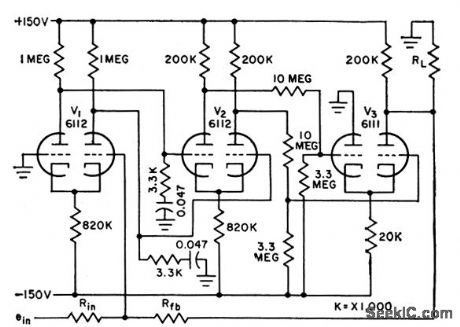
400_V_OUTPUT_SWING_WITH_TRANSISTORS
Published:2009/7/15 5:03:00 Author:Jessie
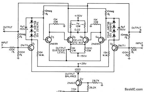
Direct-coupled differential voltage amplifier gives gain of 100 as low-frequency oscilloscope amplifier. Drift is less than 1V over normal room temperature range. Output quiescent level is 0V to ground, peak noise level is 3V, and bandwidth is 5 kc. Amplifier is not damaged by shorted output, overdrive, or supply voltages applied in any sequence.-C. L. Benson, 400,Volt Output Transistor Amplifier, EEE, 14:8, p 168. (View)
View full Circuit Diagram | Comments | Reading(930)
HOLD_AMPLIFIER
Published:2009/7/14 3:34:00 Author:May
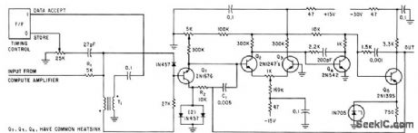
Samples output of compute amplifier at end of each word, to provide d-c output for serial decoder and permit timesharing of computer amplifier. Full-scale output is -10 v d-c.-R. M. Centner and J. R. Wilkinson, New Approach to Serial Decoding. Eliminates Static Storage, Electronics, 35:34,p 32-35. (View)
View full Circuit Diagram | Comments | Reading(676)
±5_V_USING_OPAMP
Published:2009/7/15 20:47:00 Author:Jessie
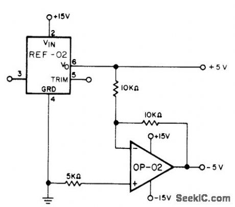
Precision Monolithics REF-02 voltage reference provides +5 V directly, while OP-02 inverting opamp provides -5 V.- +5 V Precision Voltage Reference/Thermometer, Precision Monolithics, Santa Clara, CA, 1978, REF-02, p 6.
(View)
View full Circuit Diagram | Comments | Reading(953)
INTEGRATED_CIRCUIT_DIFFERENTIAL_AMPLIFIER
Published:2009/7/15 20:32:00 Author:Jessie
Common-mode output is 0.5mV peak-to-peak, differential gain is 540, and common-mode rejection is 120 db at 60 cps in Amelco D13001: monolithic integrated circuit.-T. Prosser, How to Measure Differential. Amplifier Common-Mode Rejection, EEE, 12:7, p 74-75. (View)
View full Circuit Diagram | Comments | Reading(815)
VARIABLE_GAIN_DIFFERENTIAL
Published:2009/7/15 20:30:00 Author:Jessie
R1 controls gain. High dynamic impedance of constant-current source gives differential amplifier Q1-Q2 high common-mode rejection ratio.-G. Beene, Variable Resistor Controls Differential Amplifier Gain, Electronics, 37:29, p74. (View)
View full Circuit Diagram | Comments | Reading(849)
HARMONIC_MIXER
Published:2009/7/15 20:24:00 Author:Jessie
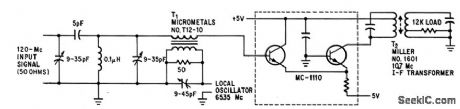
MC-1110 differential amplifier integrated circuit cancels odd-order harmonics while mixing. Local oscillator operates at half of mixing frequency. Conversion gain is 33 db from 120Mc to 10.7 Mc.-R. Hirschfeld. IC'S Improve Differential Amplifiers-and Vice Versa,Electronics.38:16.p75-79. (View)
View full Circuit Diagram | Comments | Reading(0)
CANCELLING_POWER_SUPPLY_VARIATIONS
Published:2009/7/15 20:22:00 Author:Jessie
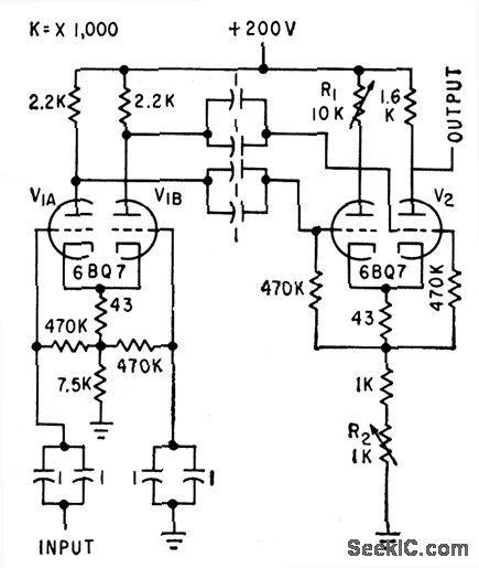
Differential amplifiers in cascade cancel output error caused by supply fluctuations, to permit low-level signal amplification.-J. Holtzman, Reducing Errors Caused by Power-Supply Variations, Electronics, 32:29, p 54-55. (View)
View full Circuit Diagram | Comments | Reading(731)
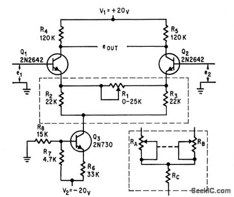
TWO_STAGE_DIFFERENTIAL_AMPLIFIER_WITH_COMMON_MODE_FEEDBACK
Published:2009/7/15 20:21:00 Author:Jessie
Feedback arrangement provides significant reduction in temperature drift of bias circuits. Voltage gains of several thousand are possible.- Transistor Manual, Seventh Edition, General Electric Co. 1964, p 119. (View)
View full Circuit Diagram | Comments | Reading(898)
15_W_POWER_AMPLIFIER_FOR_440_MHz
Published:2009/7/14 3:28:00 Author:May
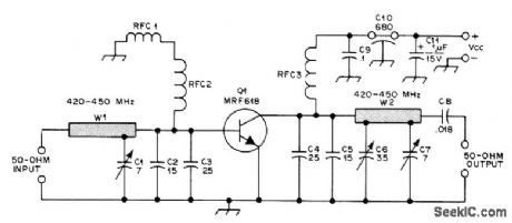
Power gain of 10 dB increases effective range of amateur transmitter. Narrow-band amplifier using Motorola MRF618 internally matched 12.5-V controlled-a transistor can be tuned from 430 to 450 MHz. Multiple L sections using 50-ohm microstrip line and mica compression variable capacitors provide input-match and collector-load transformations. Article gives printed-circuit board layout for U-shaped 0.112-inch-wide stripline inductors W1 and W2. RFC1 is ferrite bead, RFC2 is 8 turns No. 22 enamel closewound on 1/8-inch form, and RFC3 is 4 turns No. 22 enamel closewound on 1/4-inch form.-R. Olsen, Build This Solid-State PA for 440 MHz, QST, Feb. 1977, p 37-38. (View)
View full Circuit Diagram | Comments | Reading(2202)
BALANCED_DIFFERENTIAL_OPERATIONAL_AMPLIFIER
Published:2009/7/15 20:19:00 Author:Jessie
Open-loop gain is above 5,000 into 10,000-ohm load. Good stability and summing accuracy are obtained with closed. loop gains of 0.1 to 100. Provides 50-V out-put voltage swing for integrating or differentiating in control systems. Phase lag of 5° at 20 cps with closed-loop gain of 10 pre dudes use in high-frequency control systems.-L. S. Klivans, D-C Amplifiers for Control Systems, Electronics, 31:47, p 96-100. (View)
View full Circuit Diagram | Comments | Reading(901)
DIFFERENTIAL_AMPLIFIER_1
Published:2009/7/15 20:17:00 Author:Jessie
Single-stag e configuration for monolithic construction uses bleeder resistors with Darlington input transistors to increase bandwidth and gain. Current source is biased from separate bias resistor to increase output amplitude. Minimum differential voltage gain of Micronet 203 version is 100 and minimum bandwidth is 500 kc.-C. L. Heizman and D. G. Paterson, Circuit Analysis: A Monolithic Integrated Operational Amplifier, EEE, 13:5, p 80-84. (View)
View full Circuit Diagram | Comments | Reading(919)
F_M_LIMITER
Published:2009/7/15 20:07:00 Author:Jessie
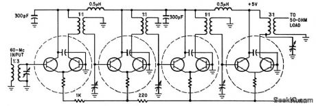
Four differential-amplifier integrated circuits serve as 60.Mc i-f f-m limiter having 6-Mc bandwidth and 80 db power gain.-R. Hirschfeld, IC's lmproveDifferential Amplifiers-and Vice Versa.Electronics.38:16,p75-79. (View)
View full Circuit Diagram | Comments | Reading(769)
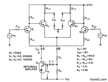
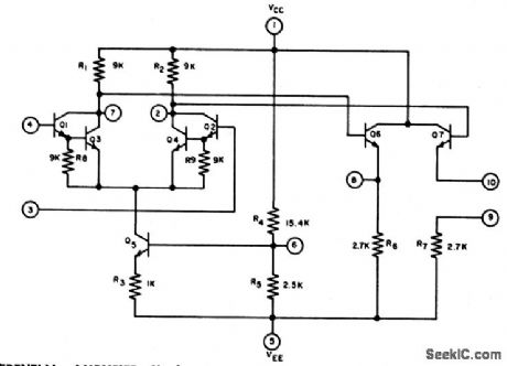
51_DB_POWER_GAIN_FOR_AUTOPILOT
Published:2009/7/15 20:06:00 Author:Jessie
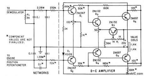
Two differential stages,Q1-Q2 and Q3-Q4,drive two emitter-followers Q5 and Q6 which in turn drive valve coils in pitch and yaw channels of autopilot.-J. H. Porter. Miniaturized. Autopilot System for Missiles.Electronics.33:43,p60-64 (View)
View full Circuit Diagram | Comments | Reading(1551)
GAIN_PROGRAMMABLE_AMPLIFIER
Published:2009/7/14 3:14:00 Author:May
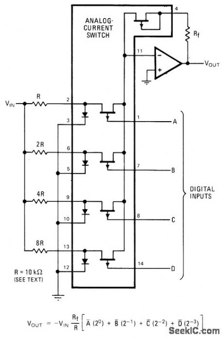
National AH5010 4-bit current-mode analog switch for TTL input is used with general-purpose opamp such as LM118 to give multiplying D/A converter at low cost. For CMOS control logic, use AM97C10 switch. Use of 10K for gain-programming resistor R gives compromise between switch resistance and switch leakage. Use 0.2% tolerance resistors for R and 2R, 0.5% for 4R, and 5% for highest resistance, with 0.1% tolerance for feedback resistor Rf which is also 10K, to give overall accuracy within 0.2%.-J. Maxwell, Analog Current Switch Makes Gain-Programmable Amplifier, Electronics, Feb. 17, 1977, p 99 and 101. (View)
View full Circuit Diagram | Comments | Reading(938)
SENSE_AMPLIFIER
Published:2009/7/15 5:36:00 Author:Jessie
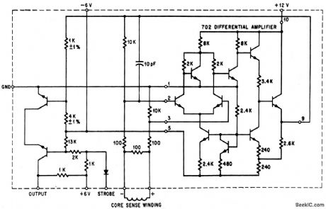
Uses two flatpacks (shaded areas)attached to thick-film passive network.-F. A. Plemenos. The packaging Revolution, Part VI: Converting to Microelectronics. Electronics.39:4,p103-109. (View)
View full Circuit Diagram | Comments | Reading(1117)
WIDE_DYNAMIC_RANGE_DIFFERENTIAL_AMPLIFIER
Published:2009/7/15 5:34:00 Author:Jessie
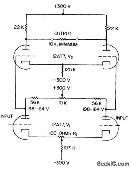
Used in amplifying and measuring small differences between two large voltages, either of which may be up to 100V above ground. Amplification of difference voltage is 250. Frequency response is within 3 db from d-c to 250 kc.-D. D. Davis, High Dynamic Range Differential Amplifier, Electronics, 31:5, p 64-66. (View)
View full Circuit Diagram | Comments | Reading(822)
DIFFERENTIAL_CURRENT_AMPLIFIER
Published:2009/7/15 5:33:00 Author:Jessie
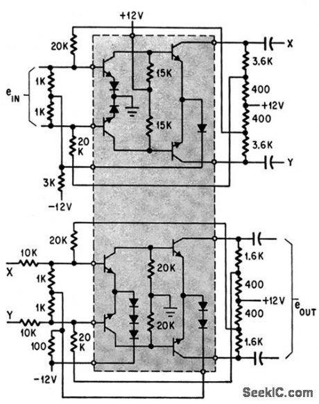
Uses eight npn transistors and eight diodes.-D. D. Robinson, Linear Microcircuits Scarce? Now You Can Breadboard Your Own, Electronics, 37:27, p. 58-64. (View)
View full Circuit Diagram | Comments | Reading(797)
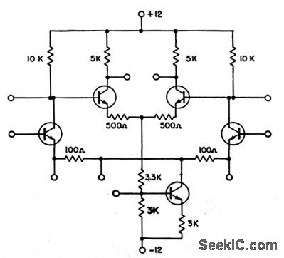
FOUR_STAGE_DIFFERENTIAL_AMPLIFIER
Published:2009/7/15 5:29:00 Author:Jessie
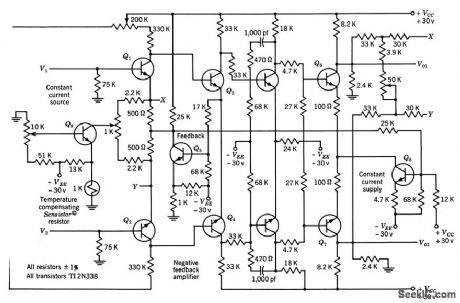
Designed for maximum open-loop amplification of differential signal. Series-shunt negative feedback provides high input impedance and low output impedance. Responds to differential signal of 25 microvolts superimposed on common level that varies from 0 to 5V. Voltage gain is continuously variable from 100 to 500. Frequency response is flat within 1% from d-c to 1,000 cps. Ideal for telemetering systems.-Texas Instruments Inc. Transistor Circuit Design, McGraw-Hill, N. Y., 1963, p 138. (View)
View full Circuit Diagram | Comments | Reading(1045)
COMPUTE_AMPLIFIER
Published:2009/7/14 3:05:00 Author:May
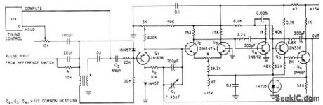
Converts digital output of reference switch for switch decoder to equivalent analog voltage and holds voltage for transfer to hold amplifier.-R. M, Centner and J. R. Wilkinson, New Approach to Serial Decoding Eliminates Static Storage, Electronics, 35:34, p 32-35. (View)
View full Circuit Diagram | Comments | Reading(649)
DIFFERENTIAL_AMPLIFIER
Published:2009/7/15 5:27:00 Author:Jessie
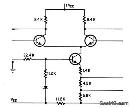
Use of transistor in place of emitter resistor gives tenfold increase in impedance of emitter circuit, up to 200,000 ohms, while using only 1% of substrate area that would be needed by film resistor of this size.-R. Hirschfeld, IC's lmprove Differential Amplifiers-and Vice Versa, Electronics, 38:16, p 75-79. (View)
View full Circuit Diagram | Comments | Reading(0)
| Pages:72/250 At 206162636465666768697071727374757677787980Under 20 |
Circuit Categories
power supply circuit
Amplifier Circuit
Basic Circuit
LED and Light Circuit
Sensor Circuit
Signal Processing
Electrical Equipment Circuit
Control Circuit
Remote Control Circuit
A/D-D/A Converter Circuit
Audio Circuit
Measuring and Test Circuit
Communication Circuit
Computer-Related Circuit
555 Circuit
Automotive Circuit
Repairing Circuit