
Amplifier Circuit
Index 76
105_MC_I_F_WITH_2N2966
Published:2009/7/16 2:51:00 Author:Jessie
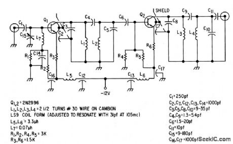
Proper loading gives good stability while providing 38 db power gain in two stages, with bandwidth of 8 Mc and noise figure of 2.5 db.-Texas Instruments Inc., Solid-Slate Communications, McGraw-Hill, N.Y., 1966, p 314. (View)
View full Circuit Diagram | Comments | Reading(707)
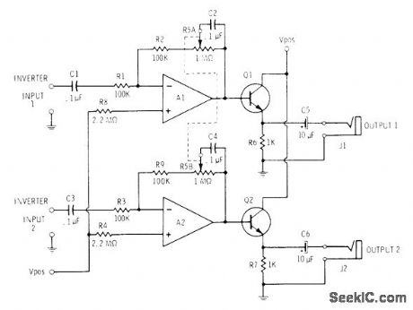
INVERTING_POWER_AMPLIFIER
Published:2009/7/13 6:02:00 Author:May
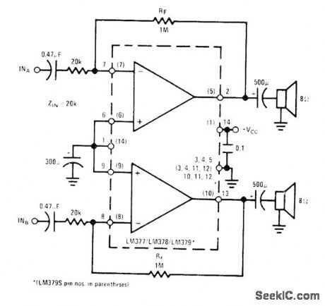
Single National LM377 IC provides 2 W per channel with 18-V supply for driving loudspeakers when fed by stereo demodulator of FM receiver. Similar LM378 chip gives 3 W per channel with 24-V supply, and LM379 gives 4 W per channel with 28-V supply. Gain is 50 for all. Heatsink is required.- Audio Handbook, National Semi-conductor, Santa Clara, CA, 1977, p 4-8-4-20. (View)
View full Circuit Diagram | Comments | Reading(0)
NONINVERTING_POWER_AMPLIFIER
Published:2009/7/13 6:01:00 Author:May
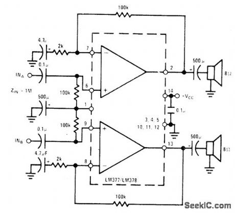
Single National LM377/LM378 provides gain of 50 and 3 W per channel for driving loudspeakers. Supply is 24 V. High input impedance permits use of high-impedance tone and volume controls. Heatsink is required,- Audio Handbook, National Semiconductor, Santa Clara, CA, 1977, p 4-8-4-20. (View)
View full Circuit Diagram | Comments | Reading(0)
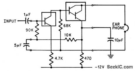
HEADPHONE_AMPLIFIER
Published:2009/7/13 5:58:00 Author:May
Designed to drive medium- to high-impedance headphones. Add matching transformers having 1000-ohm primaries if using low-impedance headphones. Dual 1-megohm pot controls gain in stereo channels over range of 1 to 100. Use 9-15 V well-filteredsupply rated at least 20 mA. Use Motorola MC3401P or National LM3900 quad opanp and 2N2924 or equivalent NPN transistor.-C. D. Rakes, Integrated Circuit Projects, Howard W. Sams, Indianapolis, IN, 1975, p 21-24. (View)
View full Circuit Diagram | Comments | Reading(0)
VIDEO_I_F_USES_FRAME_GRID_6GK7
Published:2009/7/16 2:50:00 Author:Jessie
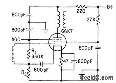
Negative voltage on suppressor controls gain of dual-control sharp-cutoff pentode. Cathode cur rent is independent of agc, and control grid bias automatically adjusts to prevent modulation clipping.-L. Solomon, New Tubes and Circuits for Consumer Electronics, Electronics, 36:2, p 47-49. (View)
View full Circuit Diagram | Comments | Reading(716)
SYMMETRICAL_LIMITING_RADAR_I_F_AMPLIFIER
Published:2009/7/16 2:50:00 Author:Jessie
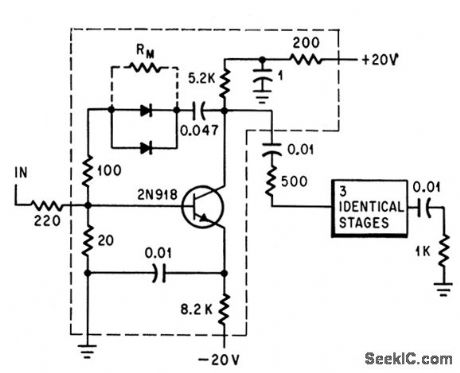
Four-stage i-f using silicon planar epitaxial transistors gives 35 db suppression of second harmonic for input of 0.3 to 30 mV. With one more stage and resistor RM across feedback diode, total phase shift is less than 25 deg.-R. F. Kirkpatrick and R. C. Stouffer, Symmetrical Limiting I-F Reduces Second Harmonic, Electronics, 37:12, p 72-73. (View)
View full Circuit Diagram | Comments | Reading(913)
10_MC_SUPERREGENERATIVE_I_F
Published:2009/7/16 2:49:00 Author:Jessie
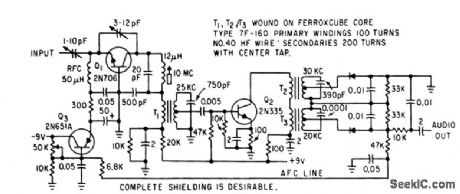
Grounded-base oscillator Q1 is self-quenched at 25 kc. Quench wave is amplified by Q2 and detected in modified Travis discriminator T2-T3.Afc voltage developed at discriminator is fed back to Q3 to maintain emitter current of Q1 at required value for quench rate.-N. H. Brown, Improved Superregenerator has Quench Converter, Electronics, 35:38, p 53. (View)
View full Circuit Diagram | Comments | Reading(1186)
30_MC_I_F_STRIP
Published:2009/7/16 2:48:00 Author:Jessie
Gain is 70 db for 3-Mc bandwidth, using 2N1405 transistors. Design equations are given.-Texas Instruments Inc., Transistor Circuit Design, McGraw-Hill, N.Y., 1963, p 276. (View)
View full Circuit Diagram | Comments | Reading(819)
30_MC_I_F_USING_2N2410
Published:2009/7/16 2:39:00 Author:Jessie
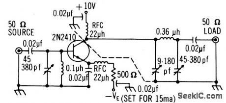
Single stage gives power gain of 16 db, permitting use as final stage of i-f strip.-Texas Instruments Inc., Solid-State Communications, McGraw-Hill, N.Y., 1966, p 308. (View)
View full Circuit Diagram | Comments | Reading(764)
30_MC_I_F_USING_2N2188
Published:2009/7/16 2:39:00 Author:Jessie
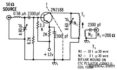
Circuit includes L-section to give generator resistance of 350 ohms from 50-ohm source. Power gain is13 db, noise figure 4 db, and bandwidth 5 Mc.-Texas Instruments Inc., Solid-State Communications, McGraw-Hill, N.Y., 1966, p 309. (View)
View full Circuit Diagram | Comments | Reading(792)
LOW_OUTPUT_IMPEDANCE_I_F
Published:2009/7/16 2:36:00 Author:Jessie

Can provide impedances as low as 2 ohms and low noise figure, to take advantage of superior noise performance of backward diodes as mixers and detectors while overcoming their very low impedance at intermediate frequencies in range from 1 kc to 100 kc. Used in continuous-wave doppler radar systems.-R. O. Wright, New Twist for Backward Diode: Help from Low-Noise Amplifier, Electronics, 39:14, p 74-77. (View)
View full Circuit Diagram | Comments | Reading(773)
I_F_WITH_LOW_PASS_FILTER
Published:2009/7/16 2:35:00 Author:Jessie
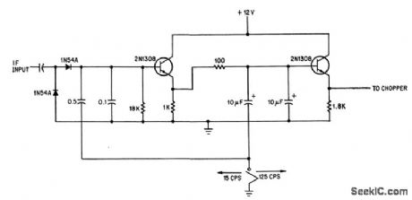
Cutoff frequency of signal-channel amplifier for frequency-measuring spectrum analyzer is 15 cps with RC fiber as shown and 125 cps when switch grounds lowest filter lead.-C. W. Wilson, Phase-Locked Marker Improves Spectrum Analyzer's Accuracy, Electronics, 39:3, p 88-92. (View)
View full Circuit Diagram | Comments | Reading(794)
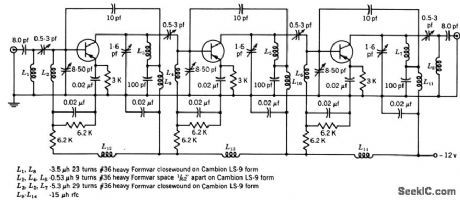
THIN_FILM_LOG_I_F_AMPLIFIER
Published:2009/7/16 2:34:00 Author:Jessie
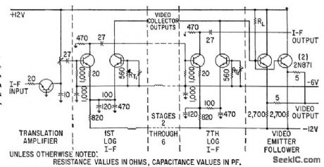
Translation ampliter limits bandwidth at input, while video emitter-follower matches 10-v output to load. All seven log i-f stages use thin-film circuits.-R. Leslie and T. Townsend, Inductors No Problem: New Thin-film Amplifier, Electronics, 36:23, p 46-49. (View)
View full Circuit Diagram | Comments | Reading(709)
70_MC_LOW_NOISE_I_F
Published:2009/7/16 2:34:00 Author:Jessie
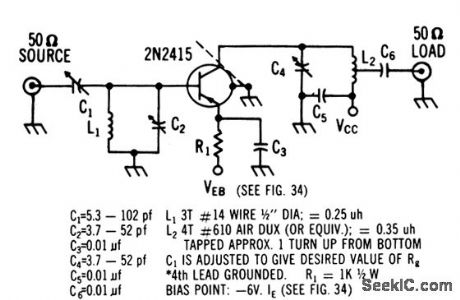
Noise figure ranges from 2 to 4 db depending on generator re sistance and emitter current. Power gain is 24 db.-Texas Instruments Inc., Solid. Slate Communications, McGraw-Hill, N.Y., 1966, p 312. (View)
View full Circuit Diagram | Comments | Reading(710)
TWO_STAGE_OPERATIONAL_AMPLIFIER
Published:2009/7/16 3:48:00 Author:Jessie
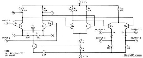


Maximum gain at room temperature is 36,000.Emitter-follower output stages are used with zener diodes to shift d-c level. Input stage uses Darlington inputs. Input impedance is above 1 meg. Frequency rolloff of 6 db/octave begins at 50 kc.-C. L. Heizman and D. G. Peterson, Circuit Analysis: A Monolithic Integrated Operational Amplifier, EEE, 13:5, p 80-84. (View)
View full Circuit Diagram | Comments | Reading(953)
AUDIO_AMPLIFIER
Published:2009/7/16 3:47:00 Author:Jessie
Uses Mitsubishi chromium-silicon and nickel-chromium thin-film resistors in hybrid arrangement with conventional transistors.-Y. Tarui, Japan Seeks Its Own Route to Improved IC Techniques, Electronics, 38:25, p 90-98. (View)
View full Circuit Diagram | Comments | Reading(0)
INTEGRATED_p_MOST_BROADBAND_AMPLIFIER
Published:2009/7/16 3:47:00 Author:Jessie
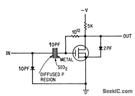
Hole-conducting metal-oxide semiconductor transistor (p-most) and metal-oxide semiconductor capacitor give gain of 5 down to a few cps for integrated stage.-F. M., Wanlass, Novel Field-Effect Device Provides Broadband Gain, Electronics, 36:44, p 30-33. (View)
View full Circuit Diagram | Comments | Reading(625)
TWO_STROBE_SENSE_AMPLIFIER
Published:2009/7/16 3:46:00 Author:Jessie
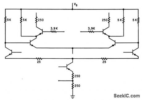
Seven-transistor sense amplifier on single 61 by 70-mil silicon chip has overall gain of 200.-M. F. Wolff, Computer in the Microcircuit Design Room, Electronics, 37:12, p 100-104. (View)
View full Circuit Diagram | Comments | Reading(641)
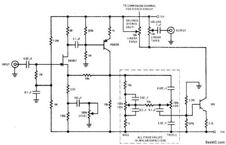
VOICE_AMPLIFIER
Published:2009/7/16 3:45:00 Author:Jessie
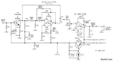
Includes audio preamp, RC active filter, audio output stage, and voltage regulator, operating from 12.5-V supply rated 300mA or more. Developed as low-distortion audio amplifier for communication receiver.Two taps for regulated supply provide regulated 8.5 V at 250 mA for other circuits. With filter out, changing input frequency from 300 to 3000 Hz has little effect on output. Switching in audio filter should attenuate all frequencies not in 700-Hz passband of filter. Gain is adjustable over wide range. Output will drive small loudspeaker of 4-16 ohms or headphones of 4-2000 ohms. Can also be used as test bench audio amplifier, intercom, or with code-practice oscillator. -J. Rusgrove, A General-Purpose Audio Amplifier, QST, Nov. 1976, p 32-34. (View)
View full Circuit Diagram | Comments | Reading(2477)
TRANSDUCER_D_C_AMPLIFIER
Published:2009/7/16 3:43:00 Author:Jessie
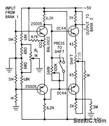
Bank 1 of 24-channel telemetry sampling switch feeds transducer outputs in sequence to heat-stabilized low-drift d-c amplifier. Output goes to bank 2, for feeding f-m subcarrier oscillator, which in turn amplitude-modulates uhf transmitter.-A. Potton, Telemetry System for Testing Automobiles, Electronics, 33:43, p 57-59. (View)
View full Circuit Diagram | Comments | Reading(786)
| Pages:76/250 At 206162636465666768697071727374757677787980Under 20 |
Circuit Categories
power supply circuit
Amplifier Circuit
Basic Circuit
LED and Light Circuit
Sensor Circuit
Signal Processing
Electrical Equipment Circuit
Control Circuit
Remote Control Circuit
A/D-D/A Converter Circuit
Audio Circuit
Measuring and Test Circuit
Communication Circuit
Computer-Related Circuit
555 Circuit
Automotive Circuit
Repairing Circuit