
Amplifier Circuit
Index 51
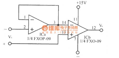
Zero-drift operational amplifier circuit
Published:2011/12/5 21:14:00 Author:Ecco | Keyword: Zero-drift , operational amplifier
View full Circuit Diagram | Comments | Reading(816)
High-voltage high -current operational amplifier circuit 3583
Published:2011/12/6 0:55:00 Author:Ecco | Keyword: High-voltage, high -current, operational amplifier
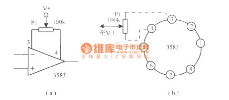
Figure (a) shows the methods for zerosetting ; Figure (b)shows the cylindrical package pin-out.
(View)
View full Circuit Diagram | Comments | Reading(889)
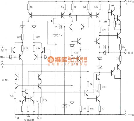
High-voltage operational amplifier circuit with internal compensation
Published:2011/12/6 0:53:00 Author:Ecco | Keyword: High-voltage , operational amplifier , internal compensation
View full Circuit Diagram | Comments | Reading(2750)
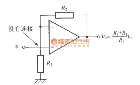
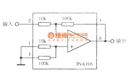
Non- inverted amplifier circuit
Published:2011/12/6 1:19:00 Author:Ecco | Keyword: Non- inverted amplifier
View full Circuit Diagram | Comments | Reading(685)
OPA604 FET input high-fidelity operational amplifier circuit
Published:2011/12/6 1:39:00 Author:Ecco | Keyword: FET input, high-fidelity, operational amplifier
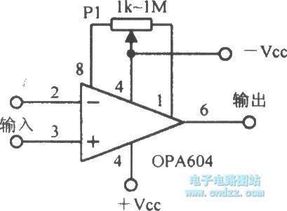
Simplified schematic diagram:
Zero wiring diagram:
(View)
View full Circuit Diagram | Comments | Reading(1750)
Balanced DC amplifier circuit using NPN and PNP
Published:2011/12/1 2:11:00 Author:Ecco | Keyword: Balanced DC amplifier , NPN , PNP
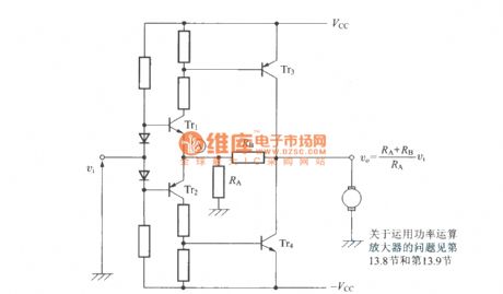
Tr3 and Tr4 can use Darlington transistors.
(View)
View full Circuit Diagram | Comments | Reading(1384)
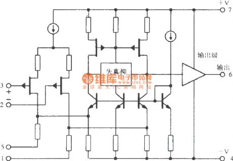
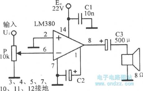
Integrated audio power amplifier circuit LM380
Published:2011/12/1 1:57:00 Author:Ecco | Keyword: Integrated, audio power amplifier
LM380 internal equivalent circuit :
LM380 application circuit:
(View)
View full Circuit Diagram | Comments | Reading(3615)
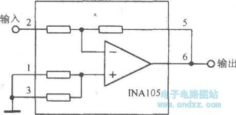
Precision unity-gain inverting amplifier
Published:2011/12/6 1:33:00 Author:Ecco | Keyword: Precision , unity-gain , inverting amplifier
View full Circuit Diagram | Comments | Reading(785)
Precision inverting amplifier circuit
Published:2011/12/5 21:26:00 Author:Ecco | Keyword: Precision , inverting amplifier
View full Circuit Diagram | Comments | Reading(714)
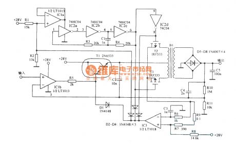
SCR driver amplifier circuit
Published:2011/12/5 21:12:00 Author:Ecco | Keyword: SCR driver amplifier
View full Circuit Diagram | Comments | Reading(3857)
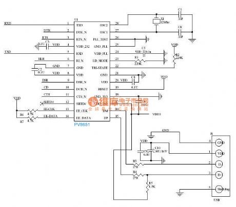
usb switching to 232 circuit
Published:2011/11/28 21:37:00 Author:Ecco | Keyword: usb , switching to 232
View full Circuit Diagram | Comments | Reading(780)
6w FM power amplifier circuit ( English)
Published:2011/11/11 2:17:00 Author:Ecco | Keyword: 6w , FM power amplifier
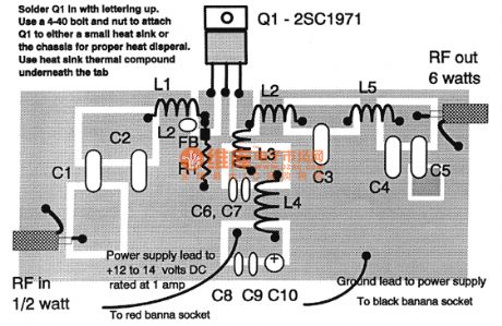
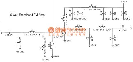
Assemble by soldering the components to the pads indicated. Keep coil, resistor, and capacitor leads as short as possible. The coils should be 3/16 to 1/4 above the board and separate turns by one wire diameter. Bend leads to form a little mounting foot for soldering to the circuit board. Tuning and power output are affected by the distance between the coil turns, you can make fine adjustments by either spreading or compressing the coil slightly. The area surrounding the pads is ground. C2, C3, C4, C6, C7, C8, C9, C10, L2, and R1 are soldered at one end to ground as well as the shield braid on the coax cables. Bolt Q1 to a small heat sink or the chassis with heat sink thermal compound or gray thermal pad underneath the tab. With an input level of 200-500mw, you should see an output of 5-6 watts. Be sure to have a proper dummy load (50 ohms) or tuned antenna connected to the output, doing otherwise will likely destroy the transistor.
(View)
View full Circuit Diagram | Comments | Reading(3127)
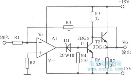
The amplifier circuit with extending bandwidth
Published:2011/12/1 1:48:00 Author:Ecco | Keyword: amplifier circuit , extending bandwidth
View full Circuit Diagram | Comments | Reading(756)
The amplifier circuit with l000V output
Published:2011/12/1 1:46:00 Author:Ecco | Keyword: amplifier circuit , l000V output
View full Circuit Diagram | Comments | Reading(769)
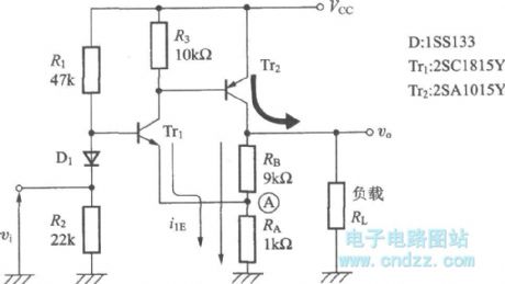
Non- reverses DC amplifier circuit using NPN and PNP
Published:2011/12/1 2:09:00 Author:Ecco | Keyword: Non- reverses, DC amplifier , NPN , PNP
View full Circuit Diagram | Comments | Reading(1284)
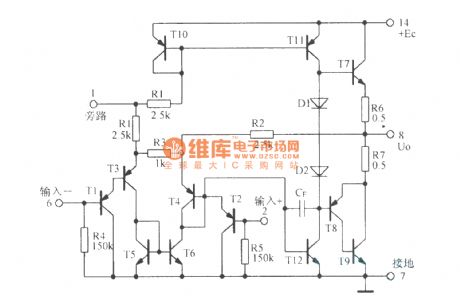
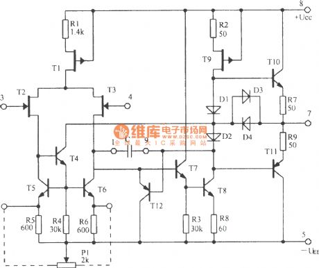
The internal circuit diagram of 5G28 integrated operational amplifier
Published:2011/12/2 1:53:00 Author:Ecco | Keyword: internal circuit , integrated operational amplifier
View full Circuit Diagram | Comments | Reading(1137)
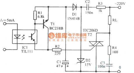
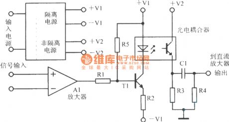
The directly optical coupling isolation amplifier circuit
Published:2011/12/2 1:51:00 Author:Ecco | Keyword: directly , optical coupling , isolation amplifier
View full Circuit Diagram | Comments | Reading(1395)
The preamp balanced amplifier circuit of Mamn-7 tube
Published:2011/12/9 1:10:00 Author:Ecco | Keyword: preamp, balanced amplifier, tube
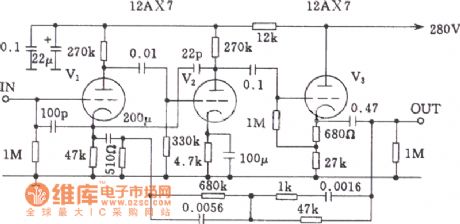
View full Circuit Diagram | Comments | Reading(2579)
The line amplifier and output stage circuit of Marantz-7 tube
Published:2011/12/9 1:13:00 Author:Ecco | Keyword: line amplifier , output stage , tube
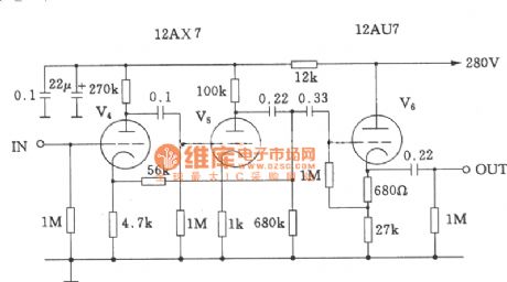
View full Circuit Diagram | Comments | Reading(2983)
The single-ended Class A 211 power amplifier circuit of high-power tube
Published:2011/12/9 1:05:00 Author:Ecco | Keyword: single-ended , Class A , power amplifier , high-power tube
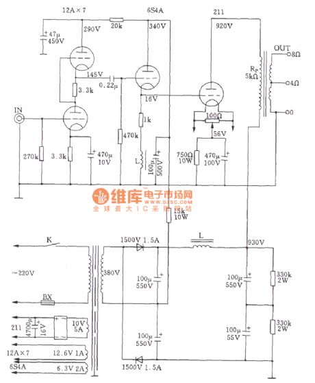
The power amplifier's total output poweris about 12W. (View)
View full Circuit Diagram | Comments | Reading(6042)
| Pages:51/250 At 204142434445464748495051525354555657585960Under 20 |
Circuit Categories
power supply circuit
Amplifier Circuit
Basic Circuit
LED and Light Circuit
Sensor Circuit
Signal Processing
Electrical Equipment Circuit
Control Circuit
Remote Control Circuit
A/D-D/A Converter Circuit
Audio Circuit
Measuring and Test Circuit
Communication Circuit
Computer-Related Circuit
555 Circuit
Automotive Circuit
Repairing Circuit