
Amplifier Circuit
Index 57
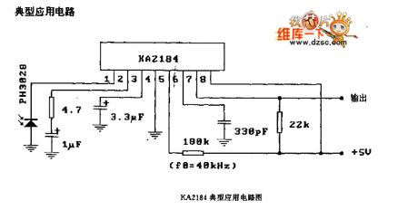
KA2184 remote control receiver preamplifier circuit diagram
Published:2011/9/8 1:52:00 Author:Ecco | Keyword: remote control, receiver preamplifier
View full Circuit Diagram | Comments | Reading(1234)
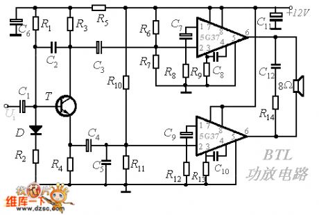
BTL integrated power amplifier circuit diagram
Published:2011/9/19 1:42:00 Author:Ecco | Keyword: BTL, integrated power amplifier
View full Circuit Diagram | Comments | Reading(2280)
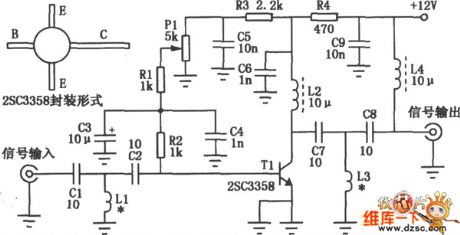
UHF amplification principle circuit diagram
Published:2011/8/31 22:31:00 Author:Ecco | Keyword: UHF amplification principle
View full Circuit Diagram | Comments | Reading(1063)
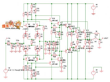
Differential power amplifier simulation circuit diagram
Published:2011/9/9 2:13:00 Author:Ecco | Keyword: Differential power amplifier, simulation
View full Circuit Diagram | Comments | Reading(1709)
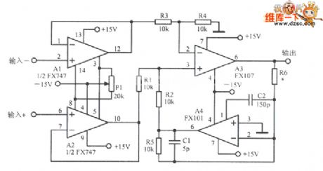
A differential amplification circuit diagram
Published:2011/9/2 1:03:00 Author:Ecco | Keyword: differential amplification
View full Circuit Diagram | Comments | Reading(840)
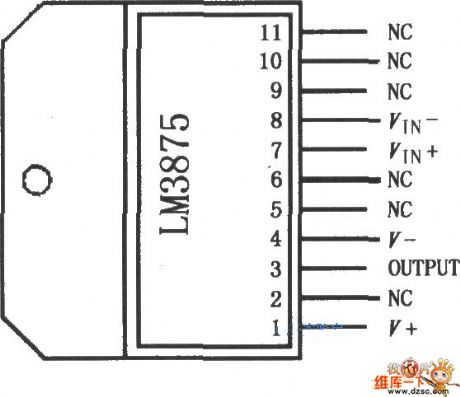
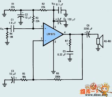
Audio power amplifier LM3875 circuit diagram
Published:2011/9/9 1:53:00 Author:Ecco | Keyword: Audio power amplifier
View full Circuit Diagram | Comments | Reading(1731)
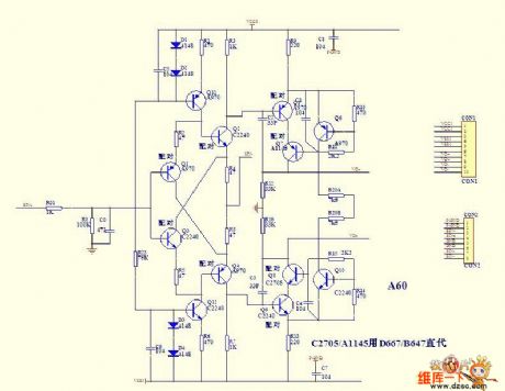
A60SCH modular amplifier circuit diagram
Published:2011/9/14 2:53:00 Author:Ecco | Keyword: modular amplifier
View full Circuit Diagram | Comments | Reading(1258)
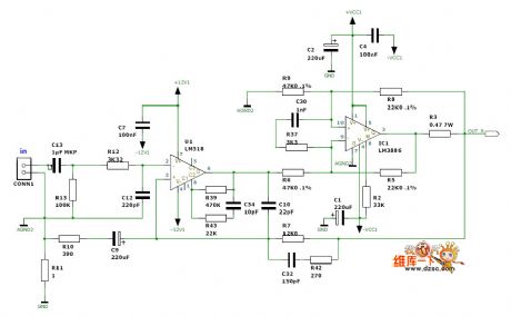
LM3886 power amplifier circuit diagram output by AUDIO
Published:2011/9/14 2:56:00 Author:Ecco | Keyword: power amplifier
View full Circuit Diagram | Comments | Reading(5113)
High-fidelity audio power amplifier LM1875 circuit diagram
Published:2011/9/13 21:16:00 Author:Ecco | Keyword: High-fidelity , audio power amplifier
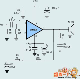
View full Circuit Diagram | Comments | Reading(4286)
power amplifier(STK6153,STK3048) circuit of thick film integrated package
Published:2011/9/15 1:42:00 Author:chopper | Keyword: power amplifier, thick film, integrated package
The picture is a power amplifition circuit of thick film integrated package.Picture (a) shows that input signal is loaded to in-phase end of STK3048 through resistace-capacity coupling circuit(resistance is 33kΩ,capacitance is 4.7μF) and it is added to the base of power tube Q1,Q2 by its output end after it is amplified by thick film power amplifier STK3048.The power amplifier adopts dynatron 2N3055 and MJ2955.R1,R2(0.25Ω) are protective resistors of common emitter. Adjusting potentiometer RP can make power tube in the stage of classA,B,and at this time,the voltage drop of R1,R2 is about 10~13mV,the quiescent current of corresponding Q1 and Q2 is 40~50mA. (View)
View full Circuit Diagram | Comments | Reading(1541)
Integrated circuit inside circuit box circuit
Published:2011/9/14 21:01:00 Author:John | Keyword: Integrated circuit, inside circuit
Features
LM331 integrated circuit is a precision frequency - voltage (also voltage - frequency) converting circuit. It includes power switch circuit, precision current source, reference power, timing comparator, RS flip-flop, input comparator, protection circuit and some other auxiliary circuit. The inside circuit box circuit is just as shown.
(View)
View full Circuit Diagram | Comments | Reading(1742)
The simplest phase shift circuit
Published:2011/9/14 6:01:00 Author:Sophia | Keyword: simplest phase shift circuit
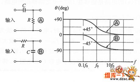
In a similar active filter circuit, usually the circuit contains the control phase circuit. This is an experiment only to change the phase of the sine wave phase-shift circuit (phase shifter) .
Following diagram shows the phase characteristics of the high-pass filter③ and low pass filter③. ③ high-pass filter can make phase shift between +90 ° ~ 0 °, while the low-pass filter ⑧ only makes phase shift between 0 ° ~ -90 °. here though phase shift is available, there is a weak point that output amplitude will change with the input frequency.
(View)
View full Circuit Diagram | Comments | Reading(1401)
Double-edge detection circuit
Published:2011/9/14 6:02:00 Author:Sophia | Keyword: Double-edge detection
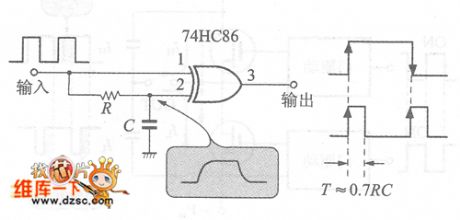
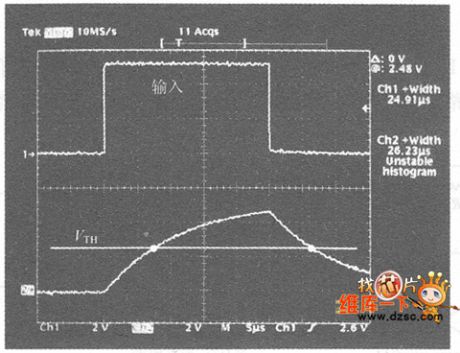
Figure 1 is the bilateral(rising and falling)detection circuit composed of XOR gate. XOR gate outputs H level when gate input terminal logic is inconsistent, for example, RC circuit easily produces delay time, the edge is detected during rising and falling, then differential pulse is outputed.
Figure 2 is the terminal voltage waveform of capacitor C. 74HC86 threshold voltage VTH is VDD / 2, the tag line is released here. From the begining of the corresponding input rising to the time to achieve the C terminal voltage VTH input, the output pulse can be obtained during the time to achieve the C terminal voltage yTH. (View)
View full Circuit Diagram | Comments | Reading(5091)
Switch delay circuit with only the delaying of rise part
Published:2011/9/14 6:03:00 Author:Sophia | Keyword: Switch delay circuit, the delaying of rise part
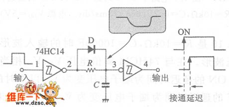
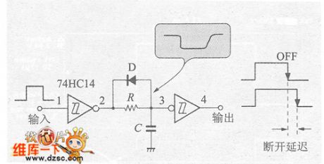
Figure 1 is the delay circuit only when the switch is ON, which is called on-delay circuit. The resistance R is in parallel with diode D, if the direction of the diode is changed, shown in Figure 2, the circuit becomes only the OFF delay time circuit- - Disconnect the delay circuit.
Figure 1 is the on-delay circuit with the delay of only rise part
Figure 2 is the off delay circuit with the delay of only the drop part The diode in the switching delay circuit reaches the action of charge and discharge time. When the diode is not conducting, T = RC; when it is conducted, CMOSIC output impedance and diode D action impedance can be neglected, which can extremely shorten time constant. (View)
View full Circuit Diagram | Comments | Reading(1189)
Controllable Voltage Regulator Circuit Diagram
Published:2011/9/14 0:25:00 Author:Zoey | Keyword: Controllable, Voltage Regulator, IC
As a controllable voltage regulator integrated circuit, S1-3090C is widely used in audios, DVD players and so on.
1 Features
S1-3090C IC consists of a +9 V voltage regulator circuit, a power on / off control circuit, and other auxiliary function circuits.
2 Pin functions and data
S1- 3090C adopts pin-4 single integrated circuit package,which has been used in Fine Refine King rear projection TVs, its pin functions of the integrated circuit and relevant data have been listed in Table 1. (View)
View full Circuit Diagram | Comments | Reading(935)
Frequency Synthesizer Circuit Diagram
Published:2011/9/14 0:26:00 Author:Zoey | Keyword: Frequency, Synthesizer Circuit Diagram
SIM8821XO2 -GOTO is a frequency synthesizer integrated circuit, it is widely used in Samsung's CDMA series cellphones, such as the Samsung A399 mobile phone.
1 Features
SIM8821XO2-GOTO integrated circuit contains the first local oscillator, the second local oscillator sampling and filtering circuit, and frequency synthesis data,start, clock circuits,phase detector power supply circuit, as well as some other auxiliary function circuits.
2 Pin Functions
Pin functions of SIM8821XO2 -GOTO IC have been listed in Table 1. (View)
View full Circuit Diagram | Comments | Reading(1146)
Three-channel Power Amplifier Circuit
Published:2011/9/14 0:08:00 Author:Zoey | Keyword: Three-channel, Power Amplifier
STK392-110 is the thick-film hybrid power amplifier integrated circuit produced by Sanyo company, they are used in the Changhong SlPT28A Rear Projection TV convergence to adjust the signal for power amplification.
STK392-110 IC-circuit block diagram has been shown in Figure 1, the integrated circuit pin functions and data has been listed in Table 1. (View)
View full Circuit Diagram | Comments | Reading(850)
Thick Film Power Amplifier Circuit
Published:2011/9/14 0:04:00 Author:Zoey | Keyword: STK392-020, Thick Film, Power Amplifier
STK392- 020are the thick film power amplifier integrated circuits produced by SANYO Company, they are widely used in rear projection TV in the adjustment of the convergence error signal for power amplification. 1 Features STK392 -020 integrated circuit includes 3 BTL power amplifier circuits, preamplifier and power amplifier power supply circuit, and other auxiliary function circuits. 2 pin functions and data STK392 -020 ICadopt 22 feet single in-line package, they are used in Changhong Fine and Refined King on the rear projection color TV (circuit number N505), the integrated circuit pin functions and data has been listed inTable 1 . Tip: STK392 a 020 ① - ③ feet should not take the negative power supply
(View)
View full Circuit Diagram | Comments | Reading(829)
High-voltage transformer drive circuit
Published:2011/9/13 20:26:00 Author:Fiona | Keyword: High-voltage, transformer
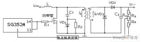
Driver circuit uses the single-ended drive working mode,this circuit is simple and its operational reliability is high.Power tube is drove by the signal from SG3524 chip. The ends of 11 and 14 pin are parallel output.When the SG3524 outputs high level,the power tube is conducted and stores energy in inductor L;When the SG3524 outputs low level,the power tube is off,it leads to the current flowing through the inductor L suddenly drops to zero,L has the potential.The pulse voltage of this counter potential is added to the input of high frequency transformer, driver transformer works.Meanwhile, the inductor L is used for impedance matching component of transformer.
(View)
View full Circuit Diagram | Comments | Reading(943)
STK392-040 Thick Film Power Amplifier Integrated Circuit Diagram
Published:2011/9/13 0:09:00 Author:Zoey | Keyword: Thick Film, Power Amplifier , Integrated Circuit Diagram
(View)
View full Circuit Diagram | Comments | Reading(842)
| Pages:57/250 At 204142434445464748495051525354555657585960Under 20 |
Circuit Categories
power supply circuit
Amplifier Circuit
Basic Circuit
LED and Light Circuit
Sensor Circuit
Signal Processing
Electrical Equipment Circuit
Control Circuit
Remote Control Circuit
A/D-D/A Converter Circuit
Audio Circuit
Measuring and Test Circuit
Communication Circuit
Computer-Related Circuit
555 Circuit
Automotive Circuit
Repairing Circuit