
Amplifier Circuit
Index 46
Simple differential amplifier circuit
Published:2012/9/11 20:26:00 Author:Ecco | Keyword: Simple, differential amplifier
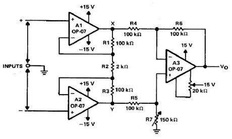
Operational amplifiers Al and A2 are connected in a noninverting configuration of their training sorties amplifier A3. The operational amplifier A3-one could call a subtractor circuit that converts the differential signal between the floating point X and Y in a single ended output voltage . Although not mandatory, amplifier A3 is usually used in unity gain and R4, R5, R6, and R7 are all equal. Joining-rejection of the amplifier A3 is a function of how the rate of R4: R5 R6 is the ratio: R7. For example, when using resistors with a tolerance of 0.1%, common mode rejection exceeds 60 dB. further improvement can be achieved by using a potentiometer (slightly higher than the value of R6) to R7. (View)
View full Circuit Diagram | Comments | Reading(3324)
Audio splitter amplifier circuit with TL084
Published:2012/9/11 20:26:00 Author:Ecco | Keyword: Audio, splitter , amplifier
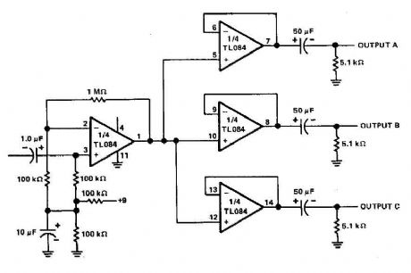
The three-channel amplifier output distribution uses a single TL084. The first step is to capacitive coupling with a p. 1.0 ~ electrolytic capacitor. The entries are railways Vee Y2 or 4.5 V. This allows using a single 9 V power supply A voltage gain of 10 (1 M ohm ohm/l00 k) is obtained in the first stage, and the other three floors are connected as a unity gain voltage followers. Each output stage drives independently via an amplifier output 50 pF capacitor to the resistance of 5.1 k ohm load. (View)
View full Circuit Diagram | Comments | Reading(7945)
Headphone Amplifier circuit
Published:2012/9/11 20:25:00 Author:Ecco | Keyword: Headphone , Amplifier
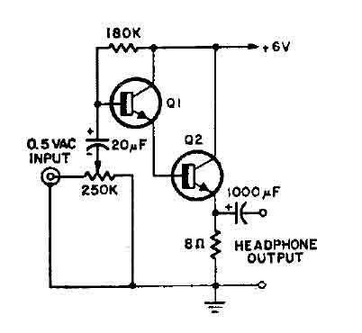
This is a simple headphone amplifier. You can use any NPN transistor. (View)
View full Circuit Diagram | Comments | Reading(4075)
High input impedance amplifier CA3440
Published:2012/9/11 20:17:00 Author:Ecco | Keyword: High input, impedance amplifier
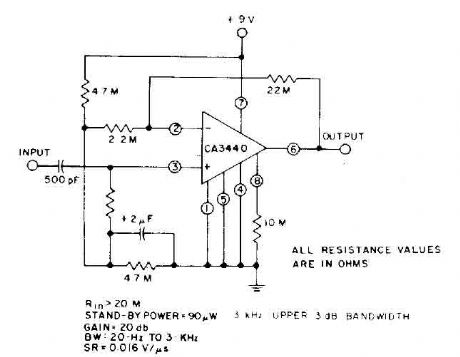
This circuit takes advantage of the leakage of low power, high input impedance, frequency and capacity of the excellent CA3440. Only one input coupling capacitor of 500 pF is needed to achieve a 20 Hz, -3 dB low frequency response. .. (View)
View full Circuit Diagram | Comments | Reading(900)
Current limiting audio amplifier circuit
Published:2012/9/11 1:38:00 Author:Ecco | Keyword: Current limiting , audio amplifier
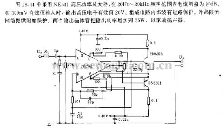
The circuit shown in Figure 18.44 uses NE541 high voltage power amplifier, and its current gain is 90dB at the frequency range of 20Hz ~ 20kHz; when it has 300mV rms input, output high voltage level RMS is 20V. The internal IC is equipped with short-circuit protection. The external current limiting network provides the additional protection. The two output transistors can increase the output power to 75W to drive the speaker.
(View)
View full Circuit Diagram | Comments | Reading(1744)
Small leakage pre-amplifier
Published:2012/9/10 21:19:00 Author:Ecco | Keyword: Small leakage, pre-amplifier
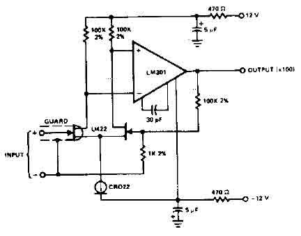
The circuit uses the LM301 has an input leakage of only 2 pA typical at 75 ° C and is used with 1 M ohm input resistance. The operating voltage has to be +-12V. (View)
View full Circuit Diagram | Comments | Reading(2642)
Stereo Preamplifier Circuit (741)
Published:2012/9/10 21:16:00 Author:Ecco | Keyword: Stereo Preamplifier
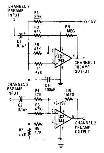
The circuit works with two 741 opamps and provides better than 20 dB gain in each channel. A better type op-amp will give a better noise figure and bandwidth. In this circuit, the sharp roll-off is at 20,000 Hertz. (View)
View full Circuit Diagram | Comments | Reading(2761)
RIAA preamplifier CA3410
Published:2012/9/10 21:15:00 Author:Ecco | Keyword: RIAA preamplifier
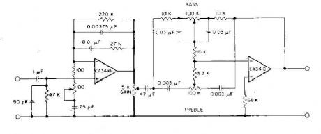
This circuit has read the RIAA equalization, tone controls, and adequate gain to drive most power amplifiers conunercial by using CA3410 op amp BiMOS. Total harmonic distortion, pushed to provide an output of 6-V, is less than 0.035% in audio-frequency range from 150 Hz to 40 kHz. Full stereo preamp is to duplicate this circuit using the CA3410 remaining two amplifiers.
Source: discovercircuits (View)
View full Circuit Diagram | Comments | Reading(3512)
Microphone preamplifier with TLC251
Published:2012/9/10 21:15:00 Author:Ecco | Keyword: Microphone preamplifier
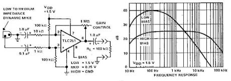
A microphone preamplifier using: om CMOS op amp with its own battery, is small enough to be placed in a case of small microphone. The amplifier operates from a 1.5V battery cathode mercury low supply currents. This preamp will operate at very low power and maintain a reasonable frequency response as well. The TLC251 is operating in low bias (operating at 1.5 V) draws a supply current of only 10 and has a year - frequency response of 3 dB 27 Hz to 4.8 kHz. With 8-pin grounded, which is designated as the polarization state high limit increases above 25 kHz. Supply current is only - 30 pA under these conditions. (View)
View full Circuit Diagram | Comments | Reading(3016)
Fully adjustable preamplifier
Published:2012/9/10 21:15:00 Author:Ecco | Keyword: Fully adjustable, preamplifier
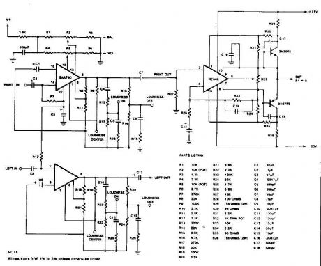
This circuit is a audio preamplifier tha has balance, tone and loudness controls. It should be suitable as an example of good design for audio application. Uses the BAA730 and NE540 chips. (View)
View full Circuit Diagram | Comments | Reading(2971)
8 Watts Audio Amplifier (TDA2003)
Published:2012/9/10 21:14:00 Author:Ecco | Keyword: 8 Watts, Audio Amplifier
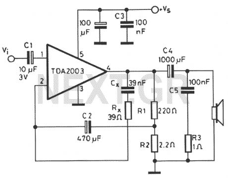
Nice small audio amplifier which use only few parts to give good quality sound. This amp can be used as a simple booster, the heart of a more complicated amplifier or used as a guitar amp. Although not perfect, this amplifier does have a wide frequency response, low harmonic distortion about 1.5%, and is capable of driving an 8 ohm speaker to output levels of around 8 watts with slightly higher distortion.
Source: discovercircuits (View)
View full Circuit Diagram | Comments | Reading(1937)
Low Power Amplifier LM386
Published:2012/9/10 21:13:00 Author:Ecco | Keyword: Low Power , Amplifier
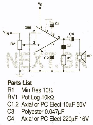
A power amp designed for use in low voltage, especially battery-operated, applications. For minimum parts count, C1 and C2 can be omitted.
Source: discovercircuits (View)
View full Circuit Diagram | Comments | Reading(1490)
1W stereo Headphone Amp (TDA2822)
Published:2012/9/10 21:13:00 Author:Ecco | Keyword: 1W , stereo , Headphone Amp

A stereo power amp designed for use in portable players and radios. A 3V supply can be used to drive headphones providing 20mW in 32 Ohms per channel.
Source: discovercircuits (View)
View full Circuit Diagram | Comments | Reading(3410)
Bomb Proof 150 Watt MOSFET Power Amplifier
Published:2012/9/10 21:12:00 Author:Ecco | Keyword: Bomb Proof , 150 Watt , MOSFET , Power Amplifier
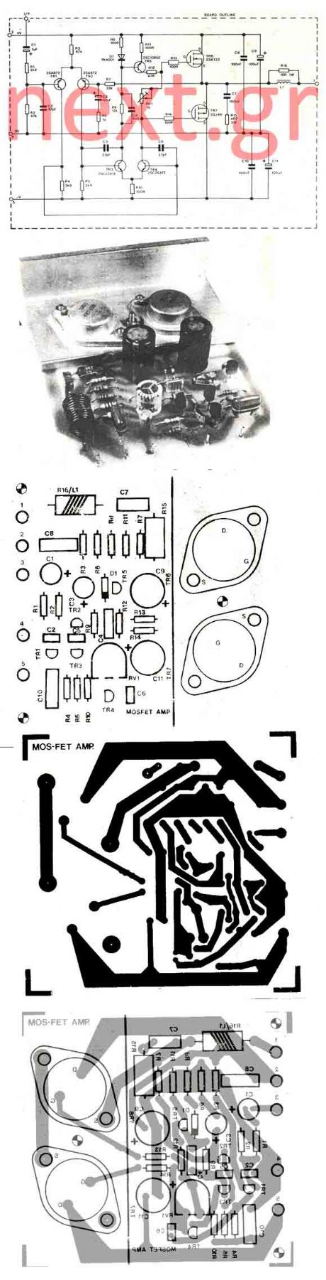
In my opinion that is the best buildable high power amplifier out there. Quality of sound is just remarkable. This is a real bomb proof amplifier like the best Valve amps. Power supply circuit is also shown. Now lets see why we are going to use MOSFETS. Thermally, the MOSFET has an advantage over the bi-polar transistor. As a bi-polar transistor heats up in use, the collector current increases due to the positive temperature coefficient of the device. If the temperature rise were allowed to continue then thermal runaway would ensue and the transistor could be destroyed. A MOSFET however exhibits a negative temperature coefficient. As the device heats up in use the Drain-Source current decreases (due to increasing internal resistance), the device temperature will also reduce in turn and the Drain-Source current will then rise again.
Source: discovercircuits (View)
View full Circuit Diagram | Comments | Reading(1528)
Stabilised amplifier schematic
Published:2012/9/10 21:11:00 Author:Ecco | Keyword: Stabilised amplifier
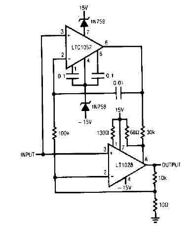
This is a ideal stabilised amplifier. It use the LT1052 and LT1028. Power supply should be double with +-15V 500mA.
Source: discovercircuits (View)
View full Circuit Diagram | Comments | Reading(732)
Fet amplifier with NPD8301
Published:2012/9/10 21:11:00 Author:Ecco | Keyword: Fet amplifier
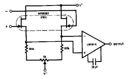
The monolithic double NPD8301 offers an ideal low offset buffer function LM10lA low drift op amp. The excellent characteristics for the track NPD8301 over its range of bias current, thereby improving common mode rejection.
Source: discovercircuits (View)
View full Circuit Diagram | Comments | Reading(844)
Auto gain control op-amp circuit
Published:2012/9/10 21:06:00 Author:Ecco | Keyword: Auto gain control, op-amp
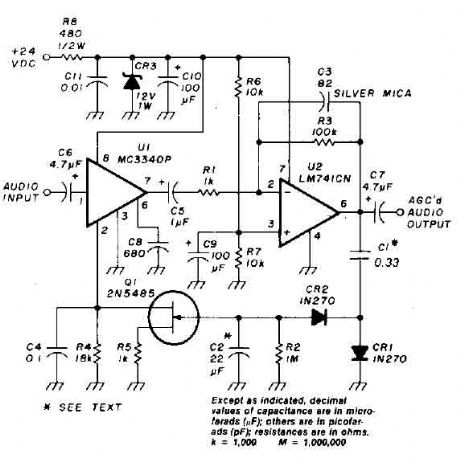
An audio signal applied to VI is passed through the operational amplifier 741, U2. After being amplified, the output signal V2 is sampled and applied to a negative voltage doubler / rectifier circuit composed of diodes CRI and CR2, with the capacitor C1. The resulting negative voltage is used as a control voltage which is applied to the door] 2N5485 FET Q1. Capacitor C2 and resistor R2 form a filter for smoothing the voltage rectified audio control. The lFET is connected between pin 2 of the MC3340P grounded by a resistor of 1 kohm.
Source: discovercircuits (View)
View full Circuit Diagram | Comments | Reading(3352)
Thermocouple Amplifier circuit (CA3193)
Published:2012/9/10 21:06:00 Author:Ecco | Keyword: Thermocouple Amplifier
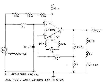
The circuit needs 15 volts and uses a precision op amp CA3193 BiMOS to amplify the signal generated more than 500 times. Three 22-megohm resistors provide large-scale output if the thermocouple opens.
Thermocouple Amplifier circuit (CA3193) (View)
View full Circuit Diagram | Comments | Reading(3443)
High fidelity amplifier circuit
Published:2012/9/10 21:03:00 Author:Ecco | Keyword: High fidelity , amplifier
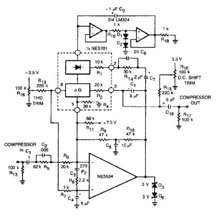
This circuit for a compressor uses a high-fidelity external op amp, and a high gain and wide bandwidth. A compensation network input is necessary for stability. The rectifier capacitor (Cg) is not grounded. but it is linked to the output of an op amp circuit.
Source: discovercircuits (View)
View full Circuit Diagram | Comments | Reading(1058)
Small current amplifier circuit
Published:2012/9/10 21:03:00 Author:Ecco | Keyword: Small current , amplifier
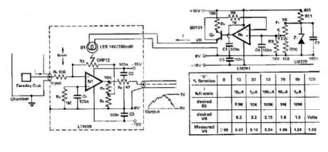
To amplify the small current signals as an electron collector inside a vacuum chamber, it is convenient for reasons of noise and bandwidth to have a head-amplifier attached to the chamber. Op N-amp 1 is a precision device with bipolar bias current and low offset voltage (1)-and the noise low, which allows the 100:1 attenuator comments to be used.
Source: discovercircuits (View)
View full Circuit Diagram | Comments | Reading(750)
| Pages:46/250 At 204142434445464748495051525354555657585960Under 20 |
Circuit Categories
power supply circuit
Amplifier Circuit
Basic Circuit
LED and Light Circuit
Sensor Circuit
Signal Processing
Electrical Equipment Circuit
Control Circuit
Remote Control Circuit
A/D-D/A Converter Circuit
Audio Circuit
Measuring and Test Circuit
Communication Circuit
Computer-Related Circuit
555 Circuit
Automotive Circuit
Repairing Circuit